
Research article · 2025 · Full text
International Journal of Agriculture and Food ScienceAnalytical design of self-propelled rotor weeder based on crop morphological parameters
Volume 7(5) · Pages 254–261 · DOI: 10.33545/2664844x.2025.v7.i5d.405 ↗
Research areasAerospace Engineering and Control Systems
Abstract
Author-writtenThe rising labor costs and declining availability of manual labor in agriculture have intensified the demand for mechanized weeding solutions. This study presents the design and development of an adjustable self-propelled rotor power weeder suitable for inter-row cultivation in light to medium-textured soils. The power requirement was primarily calculated based on soil resistance, blade dimensions and operational speed. A specific draft value of 25 N/cm was adopted for sandy loam soils, resulting in a total draft force of 2000 N per rotor. The calculated power requirement for four rotors was 3.555 kW (4.75 hp), with an additional 0.031 hp required for the drive wheels, summing to a total of 4.78 hp. Accounting for power losses, a 5.36 hp engine was selected. The rotor shaft was designed for a maximum tangential force of 2033.89 N, leading to a moment of 25423.74 N-cm. The rotor shaft diameter was determined to be 19 mm for solid shafts and 21.5 mm for hollow square shafts. The L-shaped blade with a triangular peg tooth was selected and stress analysis revealed a maximum equivalent stress of 146.77 MPa, well within the material limit for mild steel. A gear reduction mechanism was designed to reduce engine speed from 130 rpm to 65 rpm, ensuring optimal rotor speed and operator comfort. The developed weeder offers improved efficiency, operator ergonomics and adaptability across varied crop row spacings, making it a suitable solution for sustainable weed management in small to medium-sized farms.
Summary
Source-checkedPlain-language reading of the full paper, prepared with AI and checked against the text. Each point links to the authors' own words.
Why it matters
- Weed infestation is a major biological challenge in crop production because weeds compete for essential resources, leading to significant economic and yield losses. View evidence ↗
- In Indian agriculture, weed control is highly labor-intensive and expensive, consuming 900 to 1200 man-hours per hectare and representing nearly one-third of total production costs. View evidence ↗
- Using generalized weeder designs can result in higher energy use, increased damage to crops, and lower overall weeding efficiency. View evidence ↗
The question
- The study aimed to analyze the morphological parameters of four irrigated dry crops (maize, cotton, chilli, and groundnut) to design a self-propelled rotor weeder based on those parameters. View evidence ↗
What they did
- The experiment was conducted in an 800 m² field divided into four 200 m² plots (20 x 10 m each) for groundnut, maize, chilli, and cotton. View evidence ↗
- Plant height, width, and root length were measured randomly within one square meter areas at 30 and 60 days after sowing. View evidence ↗
- The weeder design assumed a specific draft of 25 N/cm for sandy loam soil, with a blade cutting width of 20 cm and a depth of 4 cm. View evidence ↗
What they found
- The calculated total power requirement for a configuration of four rotors was 3.555 kW (approximately 4.75 hp). View evidence ↗
- To account for power losses, an engine with a power of 5.36 hp (4.0 kW) was selected for the weeder. View evidence ↗
- Stress analysis of the L-shaped blade revealed a bending stress of 32.406 MPa, shear stress of 71.576 MPa, and an equivalent stress of 146.77 MPa. View evidence ↗
- A power transmission coefficient of 0.5 was used to reduce engine speed from 130 rpm to 65 rpm to match a comfortable walking speed for the operator. View evidence ↗
- Power distribution analysis showed that 88.6% of power is used by the rotors, 10.5% is lost in transmission, and 0.9% is used for the drive wheels. View evidence ↗
What it means
- The authors conclude that the developed self-propelled rotor weeder is expected to improve agricultural productivity by reducing labor needs and increasing weeding efficiency. View evidence ↗
Visual summary
1 visualsIllustrations explain the paper; they do not show study data.
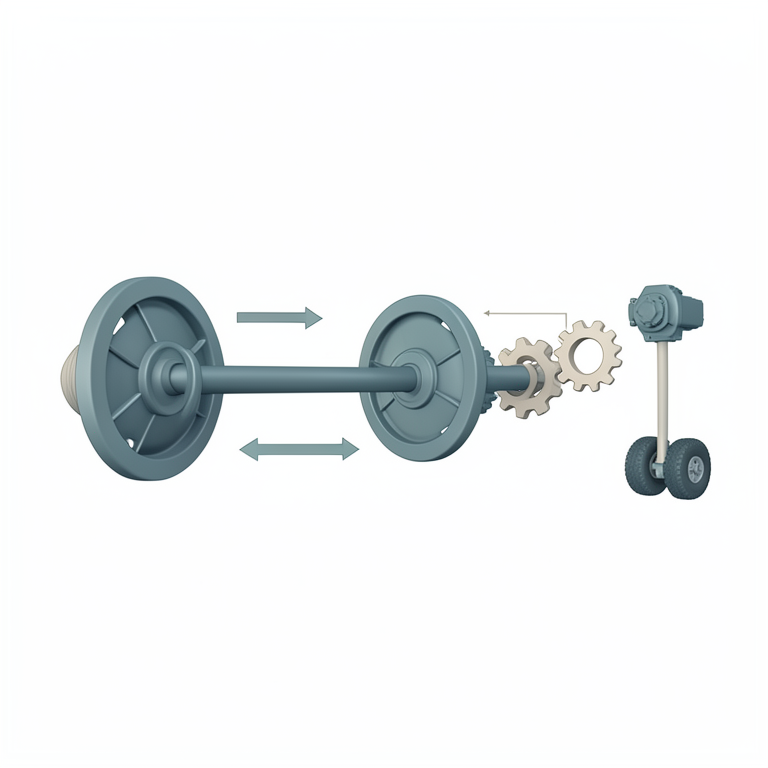
Power Distribution Flow
AI-generated conceptual illustration (self-propelled rotor weeder). It explains the idea and does not show study data.
View source evidence ↗Figures & tables
From the original paper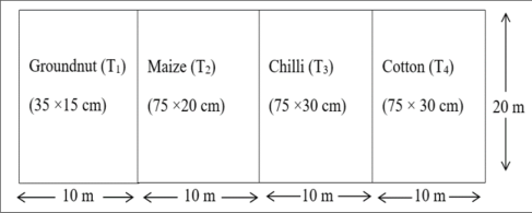 Figure 1
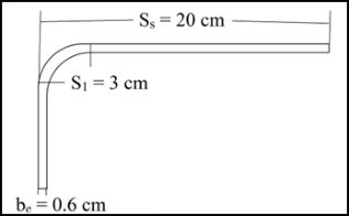 Figure 2
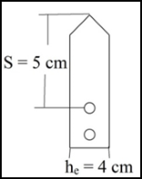 Figure 2
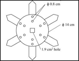 Figure 2
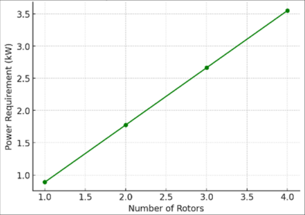 Figure 3
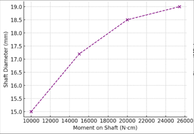 Figure 4
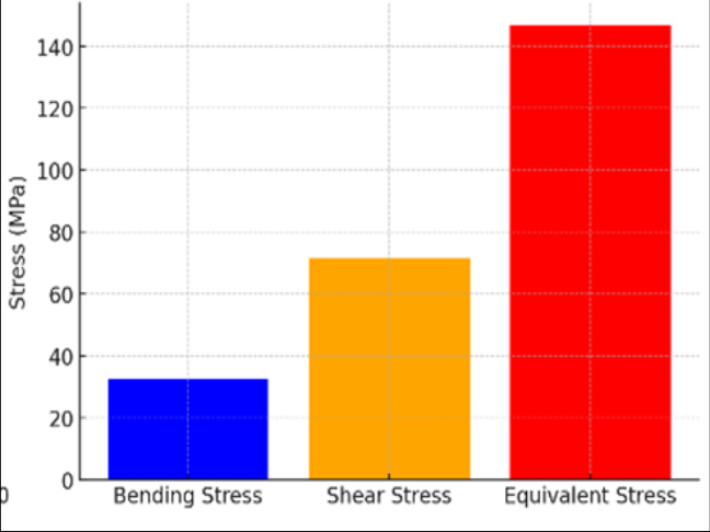 Figure 5
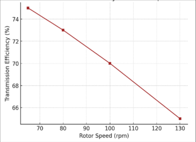 Figure 6
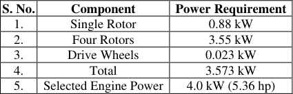 Table 1
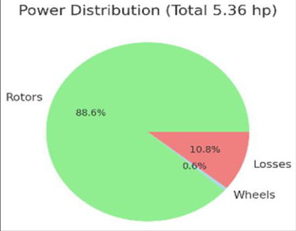 Figure 7
Introduction
Agriculture continues to be the backbone of the Indian economy, providing employment and sustenance to a majority of the rural population. As per projections by the National Commission on Population, India's population is expected to increase from 1.39 billion in 2021 to approximately 1.807 billion by 2050 (Anonymous, 2021) [3] . This significant demographic expansion demands a corresponding increase in food production, which can be met through either expansion of arable land or the adoption of efficient and sustainable farming practices. Among the major constraints in crop production, weed infestation remains one of the most pressing biological challenges, as it directly competes with crops for vital resources such as water, nutrients, sunlight and space, resulting in severe yield and economic losses (NRCWS, 2007) [13] . Weeds are estimated to contribute to about one-third of total yield losses in agricultural systems, with reported reductions ranging from 29 to 70% in maize, 40 to 45% in cotton and 30 to 40% in groundnut and chilli (Mani et al., 1968; Veerangouda et al., 2010; Rao et al., 2014) [10,24,15] . Under inadequate management, these losses can reach as high as 80% (Veerangouda et al., 2010) [24] . Moreover, weed control is among the most labor-intensive and costly operations in Indian agriculture, accounting for approximately ₹945 per hectare nearly one-third of the total production cost and consuming 900 to 1200 man-hours per hectare (Tajuddin et al., 1991; Weide et al., 2008) [23,25] . The annual economic burden from weed infestation is estimated at ₹4200 million (Natarajan, 1987) [12] . (Kanth et al., 2023) [36] studied about yield losses in groundnut crop. While mechanization has transformed agricultural operations in many developed nations, the adoption of large-scale machinery in India is constrained by the predominance of small and marginal farmers over 80% of landholdings are below two hectares. (Kanth et al., 2024) [37] was analyzed the trends and patterns of farm mechanization in India.
International Journal of Agriculture and Food Science https://www.agriculturaljournals.com (Rahaman et al., 2025) [38,39] addressed various factors which are affecting mechanization index and farm power availability. Conventional weeding methods, including manual labor and bullock-drawn implements, are not only time-consuming and physically demanding but also increasingly unsustainable due to labor shortages, rising wages and adverse climatic conditions. As a result, there is a growing reliance on mechanical weeders, particularly selfpropelled power weeders, which offer significant labor savings, increased efficiency and reduced costs (Tajuddin, 2006; Anil et al., 2014; Shekhar et al., 2010) [22,2,18] . Also studied economic analysis and feasibility of self-propelled rotor power weeder. Among mechanical weeders, the rotor weeder has emerged as a promising solution due to its rotating mechanism that uproots and buries weeds between crop rows with minimal crop disturbance. These machines are particularly suited for row crops and have gained popularity amidst increasing consumer demand for organic produce and non-chemical weed control solutions (Yadav et al., 2018) [26] . However, the effectiveness of such weeders largely depends on their adaptability to varying field conditions, especially crop morphology, soil characteristics and weed density. Generalized designs often lead to reduced weeding efficiency, higher energy consumption and increased crop damage.
Crop morphological traits such as plant height, stem diameter, row spacing, canopy structure and root anchorage play a critical role in determining the appropriate configuration of weeding equipment (Singh and Ojha, 2019) [20] . Despite this, most current weeder designs do not incorporate crop-specific morphological parameters, resulting in suboptimal field performance (Sharma and Singh, 2019; Singh and Kaur, 2021) [16,19] . With the rise of precision agriculture and the increasing availability of morphological data, there is a clear opportunity to develop crop-specific, adaptable mechanical weeders that integrate design and agronomic considerations (Patil et al., 2020; Ali et al., 2018) [14,1] . Analytical modeling provides a scientific foundation for optimizing machine design by quantitatively linking crop morphology with mechanical parameters such as rotor diameter, blade angle, operational speed and power requirements (Kepner et al., 1987; Fathollahzadeh et al., 2020) [9,6] . While some progress has been made in modeling soil-tool interactions and designing rotary tillers (Desai et al., 2022) [5] , few studies have focused on integrating crop morphological parameters into the analytical design of selfpropelled rotor weeders. This gap highlights the need for a systematic, data-driven approach to design.
The objectives of the investigation are
To study the morphological parameters of irrigated dry crops (chilli, cotton, maize and groundnut). To design the self-propelled rotor weeder based on crop morphological parameters.
Material and Methods
Material and Methods
Experimental site
The present study is conducted at Madakasira, which is located in Anantapur district of Andhra Pradesh. The geographical location of the experimental site is 13º 56'58'' N and 77º 18'42'' E with an elevation of 641.6 metres above mean sea level.
Climatic conditions
The Madakasira region is considered as one of the arid areas with low precipitation of 532 mm and the maximum temperature is 35ºC, whereas the minimum temperature of 23ºC. The average temperature is 25.7ºC. The average relative humidity is 53% and average wind speed is equal to 10.3 km h -1 .
Soil characteristics
The relative proportions of sand, silt and clay in a soil mass determine the texture of soil (sand 68.0%, silt 14.5% and clay 17.5%). Most of the Madakasira region is characterized by sandy loam soils with gravel.
Plant Height
The plant height of the four crops were measured randomly by selecting one square metre area with the help of the measuring scale at 30 and 60 days after the sowing of the crops.
Width of Plant
The plant width of the four crops were measured randomly by selecting one square metre area with the help of the measuring scale at 30 and 60 days after the sowing of the crops.
Root Length
The root length of the four crops were measured by randomly uprooting the plants in the selected one square metre area with the help of the measuring scale at 30 and 60 days after the sowing of the crops.
Design of adjustable self-propelled rotor power weeder 2.6.1 Calculation of power requirement for rotors
To calculate the power requirement for self-propelled power weeder, the soil resistance force is a major factor to consider for power calculation based on type of soil, similar way two more factors such as size of blade engaging with soil surface and speed of operation are also taken into consideration for power calculations. Certain assumptions are made to estimate power requirement, i.e., speed 1 to 1.2 km/h. specific draft is 25 N/cm for a light medium soil i.e., sandy loam soil, (Pandey, 1994) [33] . The maximum width of cut by blade is 20 cm and depth of cut is 4 cm. The belt-pulley power transmission efficiency is 70 to 75%. For weeding operation, the minimum required revolutions are 150 at which maximum tangential force will act (Niyamapa and Chertkiattipol, 2010) [32] . The furrow cross-section cut by weeder = Width of cut, cm × Depth of cut, cm = 20 × 4 = 80 cm 2 , Draft of weeder = Specific draft, N/cm × Furrow cross section, cm 2 = 25 × 80 = 2000 N, Total power requirement for one rotor of weeder in kW, is calculated according to (Thorat et al., 2014) [35] using Eq.1.
Total power = Draft × Speed Efficiency = 0.88 kW (1)
Total power requirement for 4 rotors is = 0.888 × 4 = 3.555 kW 4.75 hp
Calculation of power requirement for drive wheels
Power required for wheels is 23.12 watts (0.031 hp) was considered for the design of power weeder as given by Pandit et al. (2016) [34] and as shown in Eq.2.
The total required power for self-propelled power weeder is calculated by
Considering power losses through various ways, a higher value of 5.36 hp was selected for present study, which is equivalent to 4.0 kW.
Design of rotor shaft
The rotors maximum tangential force should be taken into account while designing the rotor shaft. Using Eq. 3, it was determined that the maximum tangential force of the blades occurs at the lowest tangential speed. Using given by (Bernacki et al., 1972) [28] .
Where, K S = Maximum tangential force, kg, C S = Reliability factor which is equal to 1.5 for non-rocky and 2 for rocky soils, N C = Power of engine, hp, ɳ C = Traction efficiency (it's value for the forward rotation of rotor shaft is 0.9), ɳ Z = Coefficient of reservation of engine power which is between 0.7-0.8 and u min = Minimum tangential speed of blades, m/s.
The tangential peripheral speed, umin was calculated by using the Eq.4.
Where, N = Revolutions of rotor, rpm and R = Radius of rotor, cm.
By using Eq.3. K S = 207.40 kg (2033.89 N)
The maximum moment on the rotor shaft (MS) is calculated by the Eq.5.
M S = K S × R=2592.5 kg cm, (25423.74 N cm) (
For design of rotor shaft or any other shaft the yield strength (σ y ) should be from 530 to 784 MPa. The rotor shaft was made from alloy steel. Using Eq.6. The allowable stress on rotor (τ all ) was calculated according to (Mott, 1985) [31] .
Where, k = Coefficient of stress concentration is 0.75, f = Coefficient of safety is 1.5, τ all = Allowable stress on rotor shaft, kg/cm and σ y = Yield stress, 730 MPa.
The required shaft diameter was calculated by using Eq.7.
The rotor shaft diameter was selected higher value as 19 mm to balance variable loads during operation for solid shaft and for hollow square shaft shown in Fig. 5 the diameter is taken as 21.5 mm.
Design of rotor blade
The type of blade, the number of blades and the functionality of the rotary weeder all affect the rotor blade design. The L-shape blade with triangular peg tooth was selected and as shown in Figure 2 was considered for the power weeder according to the working condition. The dimensions of the blade are width (4 cm), thickness (0.6 cm) and cutting width i.e., length of blade (20 cm). Thus, total length of a single gang is 40 cm. The number of rotor flanges (i) was calculated using Eq.8 given by (
Six number of blades were considered on each of the flange (Ze=6), the total number of blades was obtained using Eq.9
The soil force available at each blade (Ke) is calculated using Eq.10. Given by (Mandal et al., 2015) [30] K e = The blade dimensions are illustrated in Figure 2. The values of b e, h e, S S, S 1 and S were considered as 0.6, 4, 20, 3 and 5 cm duly. By considering blade shape, the bending stress (σ zg ), shear stress (τ skt ) and equivalent stress (σ zt ) are calculated using Eq. 11, 12 and 13 given by (Bernacki et al., 1972) [28] . The blade dimensions are fixed based on crop row-to-row distance and also on the blade orientation.
Where Equivalent stress (σ zt ) = √σ zg 2 + 4σ skt 2 = 146.77 MPa (13) The calculated values of stresses were bending stress (32.406 MPa), shear stress (71.576 MPa) and equivalent stress (146.77 MPa), while for mild steel material (Thorat et al., 2014) [35] calculated stresses were bending stress (85.40 MPa), shear stress (167.65 MPa) and equivalent (346.0 MPa) respectively.
Design of the power transmission system
Power transmission system for the self-propelled rotor power weeder is designed based on rotor and engine speeds. The coefficient of power transmission (i c ) for the power weeder was calculated using Eq.14. given by (Hemad et al., 2010) [29] .
Where, i c = Coefficient of power transmission, n d = Rotational speed of the power weeder rotor, rpm and n a = Rotational speed of the power weeder engine, rpm. To achieve the projected coefficient of speed alteration of 0.5 at full engine speed, a power transmission system should be chosen for this design. The 130 rpm is reduced to 65 rpm because which is comfortable for walking speed for operator.
Results and Discussion
Results and Discussion
Morphological parameters of irrigated dry crops 3.1.1 Chilli crop
At 30 days, chilli plants had an average height of 14.2 cm, a plant width of 9.8 cm and a root length of 6.3 cm, indicating the establishment of early vegetative structures. By 60 days, the height increased to 35.6 cm, plant width to 22.4 cm and root length to 12.8 cm, showing a significant enhancement in both shoot and root growth. The height more than doubled, suggesting favorable environmental conditions and good genetic potential. Similarly, the increased plant width reflects canopy expansion, which is essential for maximizing photosynthesis. The doubling of root length over the period indicates a healthy root system capable of supporting continued above-ground growth. Overall, chilli showed balanced and vigorous development, ideal for transitioning into reproductive stages.
Cotton crop
At 30 days, cotton plants measured 18.5 cm in height, 12.3 cm in width and had a root length of 8.1 cm. By 60 days, plant height rose to 42.7 cm, width to 25.6 cm and root length to 14.2 cm. The growth in height and width suggests good vegetative development, critical for setting up a strong framework for boll production later. Although root elongation was moderate compared to other crops, the root length nearly doubled, indicating reliable soil anchorage and water uptake capacity. The broad canopy at 60 days enhances light interception, which supports biomass accumulation. These growth trends confirm that cotton is progressing well through its vegetative phase.
Maize crop
Maize exhibited rapid growth, reaching 32.1 cm in height, 16.7 cm in width and 10.5 cm root length at 30 days. By 60 days, these values increased sharply to 78.3 cm in height, 34.2 cm in width and 21.6 cm in root length. This nearly 2.5-fold increase in height is characteristic of maize's fast vertical development during early stages. The plant width also doubled, reflecting substantial leaf expansion, vital for efficient light capture and energy synthesis. Root length growth mirrors the shoot development, indicating strong below-ground support to meet the crop's high water and nutrient demands. Maize is clearly on a vigorous growth trajectory, well-prepared for the onset of reproductive stages.
Groundnut crop
Groundnut plants recorded 12.6 cm in height, 14.5 cm in width and 7.4 cm in root length at 30 days. By 60 days, these values grew to 25.4 cm, 30.3 cm and 13.9 cm respectively. Although plant height was the lowest among the crops, the wide canopy at both stages shows groundnut's typical horizontal growth habit. The more than twofold increase in width supports soil shading and weed suppression, which are agronomic advantages. The steady increase in root length is critical for nutrient absorption and nitrogen fixation. Groundnut's overall development reflects a healthy vegetative phase, setting the foundation for flowering and peg formation. The power requirement for the rotor system was calculated considering a specific draft of 25 N/cm for sandy loam soil, a blade width of 20 cm and a depth of cut of 4 cm. This results in a furrow cross-sectional area of 80 cm². The draft force is thus 2000 N. At an operational speed of 1.2 km/h (0.33 m/s) and accounting for a belt-pulley transmission efficiency of 70%, the power requirement per rotor is approximately 0.88 kW. For a four-rotor configuration, the total power requirement is 3.55 kW (4.75 hp). The above graph (Figure 3) illustrates the linear relationship between the number of rotors and the total power requirement, emphasizing the need for appropriate engine selection based on the number of rotors used. This graph displays a clear linear relationship between the number of rotors and power consumption. As rotors increase from 1 to 4, power requirements rise proportionally from approximately 0.9 kW to 3.5 kW. This indicates that each additional rotor requires a consistent amount of additional power. This is crucial for optimizing power source selection and ensuring efficiency in the power weeder's design.
Moment (Torque) with respect to shaft diameter
The rotor shaft was designed to withstand the maximum tangential force, which occurs at the lowest tangential speed.
Using the formula provided by Bernacki et al. (1972) [28] , the maximum tangential force (K s ) was calculated as kg (2033.89 N). The maximum moment on the rotor shaft (M s ) was thus 2592.5 kg-cm (25423.74 N-cm). Considering a yield strength (σ y ) of 730 MPa for alloy steel and a safety factor of 1.5, the allowable stress (τ all ) was calculated as 210.60 MPa. The required shaft diameter was determined to be 18.44 mm and a higher value of 19 mm was selected for the solid shaft to balance variable loads during operation. The above curve (Figure 4) illustrates how shaft diameter must increase as the moment (torque) on the shaft increases.
Starting at 15 mm diameter at 10,000 N-cm, the shaft diameter grows to 19 mm at 26,000 N-cm, with the slope decreasing at higher moments. As torque increases, the shaft diameter must also increase to prevent mechanical failure. This relationship follows engineering principles for maintaining structural integrity under increasing loads. The relationship suggests a nonlinear rise, crucial for designing shafts that can withstand field stresses in weeder operations.
Different types of stress distribution pattern on blade
An L-shaped blade with a triangular peg tooth was selected for the power weeder. The blade dimensions are width, thickness and length was 4, 0.6 cm and 20 cm respectively. With six blades on each of the four flanges, the total number of blades is 24. The soil force available at each blade (K e ) was calculated as 103.7 kg (1016.94 N). The bending stress (σ zg ), shear stress (τ skt ) and equivalent stress (σ zt ) were calculated as 32.406 MPa, 71.576 MPa and 146.77 MPa, respectively. These values are within acceptable limits for mild steel material. The above graph (Figure 5) compares bending, shear and equivalent stress acting on the blade. This bar chart compares three stress types on the weeder blade are bending stress (32 MPa, blue), shear stress (72 MPa, yellow) and equivalent stress (140 MPa, red). The equivalent stress, being highest, would be most critical for material selection and safety factor calculations in the blade design. This graph helps evaluate blade material suitability and predict failure, ensuring structural reliability under field conditions.
Power transmission system effectiveness with respect to rotor speed
The graph (Figure 6) demonstrates how transmission efficiency decreases linearly as rotor speed increases. From approximately 75% efficiency at 60 RPM to 65% at 130 RPM, this negative correlation highlights the system's mechanical limitations at higher speeds, potentially due to increased friction and vibration. This inverse relationship indicates greater mechanical losses at higher speeds. It emphasizes the importance of maintaining optimal rotor speed to enhance energy efficiency and performance in the self-propelled power weeder. The power transmission system was designed based on rotor and engine speeds. The coefficient of power transmission (i c ) was calculated as 0.5, reducing the engine speed from 130 to 65 RPM, which is comfortable for the operator's walking speed.
Estimated drive wheel power requirement
The above graph shows breaking down the total power (5.36 hp) among rotors, wheels and mechanical losses. The power allocation in the system are 88.6% goes to the rotors (green), 10.5% is lost in transmission (red) and only 0.9% powers the wheels (white). This distribution emphasizes that the majority of power is appropriately directed to the primary weeding function. This breakdown aids in understanding energy utilization and identifying areas for improving efficiency in machine design. The power required for the drive wheels is minimal, estimated at 23.12 W (0.023 hp). Therefore, the total power requirement for the self-propelled power weeder is approximately 4.78 hp. Considering various power losses, a higher value of 5.36 hp (4.0 kW) was selected for the present study.
Conclusion
The design and development of the adjustable self-propelled rotor power weeder have been successfully accomplished, considering various factors such as soil resistance, blade dimensions, operational speed and power transmission efficiency. The calculated power requirements and stress analyses ensure the reliability and efficiency of the weeder in field operations. The selected engine power of 4.0 kW (5.36 hp) provides adequate performance while accommodating potential power losses. The rotor shaft and blade designs meet the necessary strength requirements, ensuring durability and effective weeding performance. Overall, the developed power weeder is expected to enhance weeding efficiency, reduce labor requirements and improve productivity in agricultural practices.
Acknowledgements
Author(s) acknowledges financial support from Dept. of Farm Machinery and Engineering, Dr. NTR College of Agricultural Engineering, Bapatla and Madakasira, Acharya N.G. Ranga Agricultural University, Lam, Guntur.
Figures and tables from the paper
| S. No. | Component | Power Requirement |
|---|---|---|
| 1. | Single Rotor | 0.88 kW |
| 2. | Four Rotors | 3.55 kW |
| 3. | Drive Wheels | 0.023 kW |
| 4. | Total | 3.573 kW |
| 5. | Selected Engine Power | 4.0 kW (5.36 hp) |
Table text extracted from the original PDF; superscript letters are shown inline. The original table image is below.
View original table image
References
39 in the original paper- Ali M, Khan A, Verma R. Rotor design optimization for dense canopy crops. J Agric Eng. 2018;55(2):89-96.
- Anil K, Kumar V, Reddy MS. Comparative performance of animal and tractor-drawn weeders. Indian J Weed Sci. 2014;46(3):234-238.
- Anonymous. Population projections for India and states 2011-2036. New Delhi: National Commission on Population, Government of India, 2021.
- Bansal RK, Verma S, Chauhan HS. Design limitations of conventional mechanical weeders. Int J Agric Mach. 2015;4(1):11-16.
- Desai P, Kulkarni M, Rao A. Optimization of rotor parameters for rotary weeders. Appl Agric Eng. 2022;61(1):101-110.
- Fathollahzadeh H, Akbarnia A, Abdi R. Analytical modeling of rotary tillage tools for energy-efficient operations. Soil Tillage Res. 2020;198:104545.
- Ghosal MK, Saha S, Das A. Status and prospects of mechanical weed control in India. Agric Rev. 2014;35(3):202-207.
- Goyal M, Arora A, Singh R. Design considerations for maize weeding tools. J Field Crops Technol. 2021;47(2):55-63.
- Kepner RA, Bainer R, Barger EL. Principles of Farm Machinery. 3 rd Ed. AVI Publishing, 1987.
- Mani VS, Gautam KC, Chakraborty TK. Weed control efficiency in different crops. Indian J Agron. 1968;13(2):129-132.
- Narayan D, Reddy AK. Performance of self-propelled weeding machines in variable soil conditions. J Agric Res. 2019;7(1):76-84.
- Natarajan S. Economic losses due to weeds. Weed News. 1987;5(1):4-7.
- NRCWS. Annual Report. Jabalpur: National Research Centre for Weed Science, 2007.
- Patil SP, Kulkarni VS, Sharma P. Precision design approach for crop-specific farm machinery. Int J Agric Sci Tech. 2020;8(2):95-103.
- Rao VS, Reddy TY, Ramakrishna YS. Crop-specific weed control strategies. Indian J Agron. 2014;59(1):1-8.
- Sharma SK, Singh R. Impact of rotor design on soybean crops. J Mech Weeding Syst. 2019;12(3):77-83.
- Sharma P, Mehta M, Singh A. Performance evaluation of inter-row rotor weeders. J Agric Mechan. 2017;48(1):45-50.
- Shekhar A, Sharma V, Prakash N. Power weeder for line sown crops. Agric Eng Today. 2010;34(4):18-22.
- Singh D, Kaur H. Evaluation of mechanical weeders in wheat and rice cropping systems. J Farm Tools Equip. 2021;16(1):20-26.
- Singh G, Ojha TP. Mechanization requirement based on crop morphology. Agric Mechanization Asia Afr Latin Am. 2019;50(2):62-67.
- Singh R, Pandey S. Mechanical crop damage due to improper weeding tool configurations. Biosys Eng Reports. 2020;9(3):122-129.
- Tajuddin A. Comparative evaluation of weeding methods. Agric Mech Dig. 2006;28(2):45-48.
- Tajuddin A, Ramesh K, Kumar P. Cost of weeding in small farms. Agric Econ Res Rev. 1991;4(1):30-36.
- Veerangouda M, Manjunatha GR, Ramalingegowda C. Impact of weed management practices on cotton International Journal of Agriculture and Food Science https://www.agriculturaljournals.com productivity. Karnataka J Agric Sci. 2010;23(2):289292.
- Weide RY, Bleeker PO, Lotz LA. Manual weeding labor requirements in organic farming. Agric Syst. 2008;97(1-2):1-11.
- Yadav A, Sharma R, Singh H. Health and environmental risks of herbicides and the need for mechanical weeding. Ind J Agric Environ. 2018;26(4):215-223.
- Zhang L, Lee J. Adaptive height control in mechanical weeders. J Smart Farming Tech. 2023;11(1):33-42.
- Bernacki H, Haman J, Kanafojski CZ. Agricultural Machines: Theory and Construction. Vol. 1. U.S. Department of Commerce, National Technical Information Service, 1972.
- Hemad KM, Kale AD, Khambalkar VP. Design of power transmission system for power tiller operated rotavator. Int J Agric Eng. 2010;3(1):115-118.
- Mandal D, Singh SP, Kumar R. Design and development of tractor-operated rotary weeder for upland crops. Int J Agric Eng. 2015;8(1):25-31.
- Mott RL. Machine Elements in Mechanical Design. 2 nd Ed. Merrill Publishing Company, 1985.
- Niyamapa T, Chertkiattipol W. Design of rotary blade for a hand tractor tillage in Thailand. Agric Eng Int CIGR J. 2010;12(1):1-10.
- Pandey KP. Principles and Applications of Agricultural Engineering. 2nd ed. Jain Brothers, 1994.
- Pandit PS, Pawar RS, Khot VM. Development of selfpropelled rotary weeder for soybean crop. Eng Technol India. 2016;7(1):23-28.
- Thorat GN, Patil SM, Kadam JR. Design and development of tractor operated rotary weeder for soybean. Int J Agric Eng. 2014;7(1):170-174.
- Kanth K, Ramana C, Reddy SJ, Edukondalu L, Reddy BR. Optimization of design parameters of electrostatic induction nozzle. Env Ecol. 2023;41(2A):1016-1022.
- Krishna Kanth B, Gowtham Deekshithulu NV, Tejaswini VV, Tejaswini V, Thomson T. Trends and patterns of farm mechanization in India. Int J Adv Biochem Res. 2024;8(10):843-856.
- Rahaman S, Vinayak M, Venkat R, Mohan SS, Babu BH. Factors affecting mechanization index and farm power availability in Guntur district of Andhra Pradesh. Ind J Agric Res. 2025;59(2):319-325.
- Rahaman S, Ramana C, Srinivasa Rao A, Ravindra Reddy B. Economic analysis and feasibility of selfpropelled rotor power weeder. J Exp Agric Int. 2025;46(2):119-125.
Cited by 1
From OpenAlex, OpenCitations and reference lists read by Scinovex
- Performance of a Battery-Powered Self-Propelled Coriander Harvester ↗
Kalluri Praveen, Srinu Banothu, Nagaraju Dharavat, Madineni Lokesh, M. Vinayak · AgriEngineering · 2025
Coriander is a significant crop, playing an essential role in daily life for various purposes, including flavouring curries and medicinal uses, among others. Despite its importance, coriander is still harvested manually. To address this, developed a self-propelled battery-operated coriander harvester, designed with ergonomics, environmental sustainability and affordability for small and marginal farmers in mind. The harvester is equipped with a…
❝ 1PDF