
Research article · 2022 · Full text
International Journal of Research in AgronomyDevelopment of a programmable digital weighing scale for agro-allied industry
Volume 5(2) · Pages 01–05 · DOI: 10.33545/2618060x.2022.v5.i2a.100 ↗
Research areasTransport Systems and Technology
Abstract
Author-writtenThe use of electronic weighing equipment offers management with fast, accurate, and timely information that enables customers to get their products quickly. The fact that it's used across the board in the business speaks volumes about how well accepted it is. In reality, its use ranges from conventional retail to manufacturing and warehousing to postal, health, and transportation services. It's a really ubiquitous technology. Microprocessor-based single-point load cell weighing devices are difficult to develop and execute because they contain a large circuitry. They are also slow and have poor resolution. Microprocessor-based weighing scales that use faster microprocessors and higher resolution are also available. As a result, these gadgets are typically prohibitively expensive since they include a large number of external devices and processors. In another electronic weighing system, an 8-bit analogue to digital converter is used in conjunction with a microprocessor. To store programs, data, and variables, it is equipped with onboard memory modules. A compromise must be made between range and resolution in both circumstances. As part of this study, we discuss the design and execution of a digital electronic weighing system that may be used in the home, the laboratory, and commercially. A microcontroller chip is used to decrease the amount of wiring in the system. To store data from the ADC, an 8-bit 8051 microcontroller is used together with a local memory module. To obtain high resolution while yet maintaining a wide dynamic range, a serial 10-bit ADC must be connected to an 8-bit microcontroller through a software interface. This is because the microcontroller utilized has an inbuilt Serial Programming Interface (SPI) built-in. Displays the weight deposited on a single point load cell are shown on an LCD screen using an electronic weighing scale. 0-5 kilograms of weight may be measured using the system that was built.
Summary
Source-checkedPlain-language reading of the full paper, prepared with AI and checked against the text. Each point links to the authors' own words.
Why it matters
- Electronic weighing equipment is widely used across various industries, including retail, manufacturing, and transportation, because it provides fast and accurate information for customers. View evidence ↗
- Traditional microprocessor-based weighing devices often suffer from slow speeds, poor resolution, and overly complex circuitry. View evidence ↗
- Many commercial weighing scales use proprietary chips, which limits their flexibility and the range of tasks they can perform. View evidence ↗
The question
- The study aimed to develop a microcontroller-based electronic weighing scale that offers high resolution and a wide dynamic range. View evidence ↗
What they did
- The system was built using an Atmel AT89S8252 microcontroller and a 10-bit serial analogue-to-digital converter (ADC). View evidence ↗
- The device utilizes a foil strain gauge-based load cell that operates on the bending principle to detect weight. View evidence ↗
- Key hardware components include an INA125 instrumentation amplifier, a TLC1549 ADC, and a 16x2 LCD for displaying results. View evidence ↗
- The microcontroller's memory configuration consists of 8 kB of flash memory for programs, 2 kB of EEPROM for data storage, and 256 bytes of internal RAM for variables. View evidence ↗
What they found
- Testing with a digital multi-meter showed that the bridge's output and input resistances remained constant at 409 and 351, respectively, regardless of the load. View evidence ↗
- The measured resistances were very close to the manufacturer's certified values of 410 and 350, indicating minimal measurement error. View evidence ↗
- The developed system can measure mass from 0 to 5 kg with a sensitivity of 40 grams per kilogram using an excitation voltage of 40 g per volt. View evidence ↗
What it means
- The authors conclude that their microcontroller-based design is more portable, adaptable, and cost-effective than existing electronic weighing balances. View evidence ↗
Figures & tables
From the original paper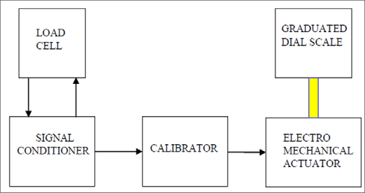 Figure 1
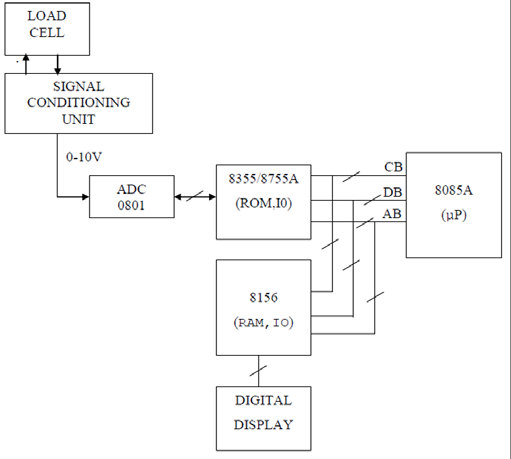 Figure 2
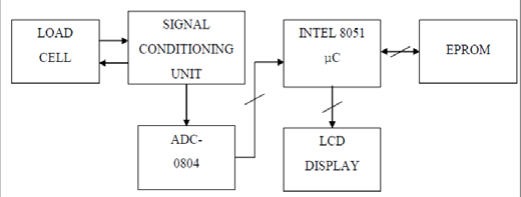 Figure 3
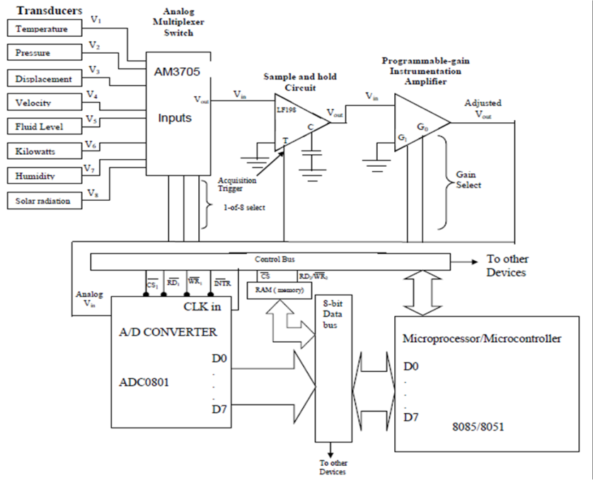 Figure 4
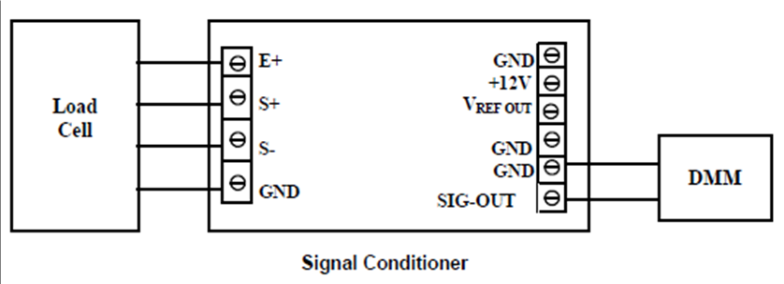 Figure 5
Introduction
Food is the third most essential need for human survival after oxygen and water. The first and second goals of the sustainable development goals (SDG's) are centered on poverty eradication and food security. The Agro-allied industry is a collection of companies engaged in a highscale. Production, processing, and packaging of food with the use of modern equipment and methods Aimed at achieving these goals. It is also a vital integral part of any nation's economic growth. A large number of design applications are built on combinational logic gates and sequential logic ICs. A traffic light controller, for example, cycles between green, yellow, and red. Some counter ICs and a shift register would be needed to create the circuit utilizing combinational and sequential logic. If a pedestrian cross-walk pushbutton interrupts the sequence, a D flip-flop is employed. If you're working with Small Scale Integration or Medium Scale Integration Integrated Circuits (ICs), you'll have no trouble finding a full solution (Kleitz, 2018) [3] . Complex electrical control applications, on the other hand, make this strategy ineffective. A contemporary car has various analogue and digital control functions, such as engine speed, manifold pressure and coolant temperature to monitor; as well as several digital control functions, such as spark plug timing and fuel mixture management. Calculations and judgments have to be made regularly, making the process even more difficult. As a result, a computer with a microprocessor would be required (Ramsay 2020) [4] . When an application requires computations, decision-making based on external stimuli, and the ability to remember prior occurrences, a microprocessor-based solution should be explored.
With a microprocessor, there are several benefits over the traditional "hard-wired" technique of using an integrated circuit (IC). For starters, the microprocessor is a general-purpose piece of hardware. The software program instructions provided by the creator give it a distinct personality. It is a potent digital problem solver due to its ability to conduct arithmetic, comparisons, and memory updates. Unlike a hard-wired system, which may have to be completely rebuilt or reconstructed, changing a few software instructions may generally make modifications to an application. However, microprocessor-based system applications have several drawbacks. Most of these applications need external support chips, resulting in excessive circuitry and expense (Houpis 2019) [2] . A microcontroller-based electronic weighing scale with a wide dynamic range and an excellent resolution was the goal of this study. It may be reprogrammed to do various functions. The 8051 microcontrollers are used to create this low-cost prototype. There are 8K bytes of flash memory in-system for storing programs and data, 2K bytes of EEPROM memory for longterm data storage and 256 RAM variables in the microcontroller that make up the final weighing balance (Source: atmel.com). The majority of electronic weighing scales now on the market employ proprietary chips, which makes them inflexible. They are only allowed to carry out a limited set of duties. Because microprocessors lack built-in memory, extra support chips are required. Their price tags are high. In most microprocessorbased weighing scales, there is a trade-off between range and accuracy. Reprogramming a microprocessor-based system is a difficult task. Since bits in memory replace electrical connections, this study makes better use of a microcontroller. The system may be reprogrammed to make any changes to the hardware design to enhance the system.
Literature review
Analogue scales now use transducer load cells or piezoelectric sensors to detect weight. As a result of the analogue nature of their outputs and the lack of a digital processor, they are known as analogue devices. Scales include either a graduated dial scale with a spinning pointer, or a calibrated rotating dial. A block schematic of an analogue weighing scale is seen in Figure 1 (Mayer, 2020).
Fig 1: Functional block diagram of an analog scale
There are several drawbacks to using this sort of scale. Because of the dial's low resolution, it is difficult to distinguish between distinct items because of the lack of precision. For one thing, the gadget does not have a storage capacity for past measurements, therefore it is only possible to remember the weight of a previously measured item mentally or by writing it down. For the third time, calibration is required for every measurement, making it tiresome and lengthy. A considerable amount of electricity is used by the electro mechanical actuator since it operates at a high voltage and last but not least, the actuator's moving components and visible high maintenance costs contribute to the machine's poor efficiency. In certain circumstances, the calibrator has been replaced with a digital processor circuitry that creates a digital signal for operating the actuator that moves the analogue dial. It is impossible to solve the poor resolution issue if this kind of dial is used. A Three-chip minimum-component 8085A microprocessor system is at the heart of the balancing circuit. For the A/D hand shaking, the 8355/8755A has two I/O ports. Load cell output signals are sent into an 8-bit ADC using a signal conditioning circuit. A suitable reference voltage will cause the ADC's binary output to rise numerically in step-like increments proportional to how much mass is placed on the load cell. Using a digital display, the binary 8-bit output must be transformed to binary-coded decimal (BCD) digits before being shown as a decimal number. For driving a digital display, the 8156 has an 8-bit port A. It takes BCD data, translates it to a seven-segment code, and then switches on the relevant segments in the driving circuit. As a result of receiving binary data from an ADC, a CPU cannot show it on the screen. To illustrate, the ADC's output is 000101002 when the weight is 20 kg. 00100000BCD must be used to show this before it can be read.
For binary to BCD conversion, MSI ICs are a good choice because of their specificity. Writing a software subroutine to conduct the conversion is an option as well.
Another option is to utilize a look-up table. Nonlinear and complicated data conversion may benefit greatly from the table look-up approach. Because it requires a lot of memory to store the table entries, it has a downside: Software can be easily constructed to do the conversion in this case since the outcomes For the user to be able to see the hexadecimal value on the LCD, the microcontroller must first do the conversion and then read the digital string.
When compared to the Intel 8085 microprocessor, the Intel 8051 micro controller is a better choice for control applications because of its poor sensitivity, absence of inbuilt EPROM, inability to rewrite program memory, high cost, and lack of an SPI serial interface. Many commercial transducers use bending load cells, which have sensing components that are bent. A comparatively modest force produces a significant strain level. Asymmetrical cross-sectional beams are always exposed to two equal stresses of opposite signs in the case of symmetrical crosssectional beams. Using this method, a complete bridge circuit may be easily created, and temperature correction is rather simple.
Variations in resistance of the gauges, which are bonded directly to the surface of the structural part (element) being tested, may be used to detect length changes. It is possible to calculate the size of the resistance change using.
Where L is the total length, A is the cross-sectional area, and ρ is the resistivity of the foil strain gauge. Taking the logarithm of the strain and the differential of both sides,
Introducing Poisson's ratio, σ, for the gauge material,
Into equation 3 yields, ( )
Equation 5 shows that resistance changes occur as a result of mechanical strain, as well as the possibility of resistivity changes. Strain gauge resistance variations may be monitored using bridge circuits because minor changes in resistance can be detected and temperature compensation is readily achieved by using two strain gauges of the same kind in neighbouring arms of the bridge. The mechanical strain is applied to one gauge, while the temperature of the strain detector is maintained at the same level as that of the other gauge. To maintain a balanced structure, temperature variations have an equivalent impact on all gauges (Brophy, 2020) [1] . When a force is applied to the material, it is somewhat compressed, which causes the strain gauge to be compressed in the direction of the sensitivity axis. The resistance of the strain gauge conductor falls as its cross-sectional area and length are squeezed. The milliohm change in resistance is transformed to a voltage and amplified before it is supplied to the ADC, which processes it. Unbalanced bridges, in contrast to Wheatstone and Kelvin bridges, need a certain amount of source voltage to operate properly, while these bridges offer measurements in a situation of perfect balance and, as a result, perform regardless of the source voltage. Due to the imbalance created by the excitation voltage per unit of force, strain gauge bridge ratings are given in millivolts. The strain gauge used to measure mass is rated at 2 mV in this study. This indicates that for every volt of excitation voltage provided, the bridge will be imbalanced by 2 mV (Kleitz, 2018) [3] .
Methodology
Automated data collecting is becoming more critical than ever in today's environment. An array of analogue inputs may be continuously monitored by computer systems, and the data collected is stored for later use. Figure 4 depicts a typical eightchannel computerized data collecting system. The data bus and the control bus are the primary means of communication for the whole system. The information-carrying capacity of a processor or microprocessor-based system is determined by the data bus. The ADC, the microprocessor/microcontroller, and the RAM are all on the data bus in this instance. To and from the different devices, the control bus transmits control signals, such as the system clock, triggers, and selects. In each of the eight transducers, the analogue quantity being measured is represented by a voltage output. Scan all values at a predetermined period, and store the digital findings in memory for future use, which is what a microprocessor/microcontroller is designed to do. Starting with the multiplexer, the microprocessor must enable and provide the correct control signals to each of the devices in turn, beginning with the ADC. Measurement must be taken at a certain point in time since analogue numbers may fluctuate so rapidly. Sample-and-hold circuit with external hold capacitor enables the system to capture (sample) and keep an analogue value at the same moment the CPU provides acquisition trigger. There are eight separate full-scale output ratings for each of the eight transducers. Pressure transducers can only measure pressures between 0 and 500 mV; temperature transducers can measure temperatures between 0 and 5 V LH0084 may be configured for gains of 1, 2, 5, or 10 through the gain chosen inputs. The microprocessor/micro controller will set the gain to 10 when it is time to read the pressure transducer so that the range is 0 to 5 volts to match the other transducers. In this approach, the ADC can always work in its most accurate range of 0 to 5 volts. The analogue-to-digital converter (ADC) takes the modified voltage and transforms it into an 8-bit binary string. Chip select (CS) and start conversion (WR or STC) pulses are used to accomplish this. Microprocessor/microcontroller provides an output enable (RD or OE) when the end-of-conversion (INTR or EOC) lines fall LOW, allowing data from the data bus (D0 to D7) to be read from the microprocessor/microcontroller and subsequently the random-access memory chip (RAM). The CPU decides when to do the next scan, and this cycle is repeated for all eight transducers at that moment. The data acquired by the microprocessor/micro controller will be used by other software processes. Many possible responses to the data collected include issuing an alarm or changing the speed of a fan, reducing energy use or raising fluid levels. Logic family compatibility, current and voltage ratings, and operating temperature all factored into the selection of hardware components for the electronic weighing balance. There are a few important components utilized in this study: INA125 instrumentation amplifier; TLC1549 ADC; AT89S8252 Controller; and a 16x2 Liquid-Crystal-Display (16x2) (LCD). The system was designed, built, programmed, and tested according to the steps outlined below.
Result
DMMs were used to monitor signal conditioner output while load cell platters were shifted in and out of position. In Figure 5, you can see how things were set up during the test.
The load cell's bridge nominal resistance was measured using a DMM in the resistance mode before the system was powered on. The DMM was used to measure the bridge resistance change at zero loads, and subsequently as the load grew. The DMM was also utilized to monitor the output voltage of the load cell while the load was altered. Using a digital multi-meter (DMM), the bridge's output and input resistances were 409 and 351. Even when the platter was loaded differently, these numbers remained constant. These are 410 and 350, respectively, according to the manufacturer's load cell calibration certificate. It is worth noting that the measurement mistakes are extremely modest. The precision and resolution of the ADC are critical to the developed system's measurement quality. The lower the input voltage, the worse the ADC's accuracy. This is because the digital signals' switching transients make the Vcc-to-digital ground lines inherently noisy. Although it's not required, using separate grounds for analogue and digital circuits protects the analogue voltage comparator from switching incorrectly owing to electrical noise and jitter. TLC 1549 ADC features two reference channels. These settings set the analogue input's top and lower limits, resulting in full scale and zero readings, respectively. These REF+ and REFvalues, as well as the analogue input, should not be higher than the positive supply or lower than GND, following the given absolute maximum ratings. It is a full scale when the input signal is equal to or higher than REF+, and at zero when the input signal is equal or lower than REF. Every ADC measurement comprises a range of inevitable, independent faults that impact its accuracy. When σi represents each independent error, the total error Can be expressed as ( )
This equation contains a variety of defects, including sensor anomalies, noise, amplifier gain and offset, ADC quantization (resolution error), and other variables. Ideally, every measurement of an analogue voltage should be represented by a single digital code with an unlimited number of digits of precision. There are tiny but limited gaps between a one-digit number and the next in a real ADC, and this quantity is determined by the ADC's lowest quantum value.
Conclusion
An inexpensive microcontroller with an integrated Serial Programming Interface (SPI) was used in this study to provide a novel idea for building a flexible electronic weighing balance that is a data collecting system (SPI). Based on an Atmel AT89S8252 microcontroller and a 10-bit ADC serial interface, the electronic balance was created. 256 bytes of internal RAM are used to store variables on the microcontroller, while 8 kB of in-system flash memory is used to store the program. The microcontroller also contains 2 kB of EEPROM memory to save data. The transducer employed is a foil strain gauge-based load cell installed to work using the bending principle. The gauge resistance varies as a load is applied to the platter. 'Load cell bridge circuitry translates this change in resistance to an electrical voltage, which is then supplied to and amplified by the INA125P instrumentation amplifier and related electronics. The ADC is connected to the signal conditioner. Design and implementation of the analogue and digital circuits on PCB boards were carried out using Express PCB software.
Programming for the MCS-51 was done using M-IDE Studio.
With the PM-51 programmer, it was "burned in" to the microcontroller. The designed microcontroller-based electronic weighing balance is less expensive, more adaptable, and more portable than currently available electronic weighing balances. An excitation voltage of 40 g per volt may be used to measure mass from 0 to 5 kg with a sensitivity of 40 grams per kilogram.