
Research article · 2021 · Full text
International Journal of Statistics and Applied MathematicsMixed convection effect on heat and mass transfer within a ‘M’ shaped closed enclosure with a heater at the bottom wall
Volume 6(5) · Pages 118–125
Research areasNanofluid Flow and Heat TransferGeothermal Energy Systems and ApplicationsHeat and Mass Transfer in Porous Media
Abstract
Author-writtenThis article deals with a numerical study of two-dimensional mixed convection heat and mass transfer within an enclosure using finite element method. The key factors for mixed convection are the Grashof number (Gr), Richardson number (Ri), and Reynolds number (Re), which are used to derive various fluid and heat transport properties inside the cavity. A simple change is employed to transfer the governing equations into a dimensionless form. Comparison with the previously published work is made and found to be an excellent agreement. The study is performed with different buoyancy ratio number and the effect of aforesaid parameters (Reynolds number, Re (=100), Lewis number, Le (= 0.1), buoyancy ratio, Br (=10,15,20) and Richardson number, Ri (= 1) for Prandtl number Pr (=0.71 and 1)) on the flow and temperature fields as well as the heat and mass transfer rate examined. The results show that the increase of buoyancy ratio enhances the heat and mass transfer rate.
Summary
Source-checkedPlain-language reading of the full paper, prepared with AI and checked against the text. Each point links to the authors' own words.
Why it matters
- Convection is the process of transferring heat through a liquid when that liquid is in motion. View evidence ↗
- Mixed convection occurs when a fluid is externally forced to flow in the opposite direction of the buoyancy force. View evidence ↗
- Studying viscous flows with corrugated walls is important for applications like missile boosters, reentry vehicle cooling, and combustion chambers. View evidence ↗
The question
- The study aims to examine mixed convection heat and mass transfer within an 'M' shaped closed square enclosure with a moving wall and varying buoyancy ratios. View evidence ↗
What they did
- The simulation used a Reynolds number of 100, Lewis number of 0.1, Richardson number of 1, buoyancy ratios of 10, 15, and 20, and Prandtl numbers of 0.71 and 1. View evidence ↗
- The model consists of a 2D square enclosure with a heated bottom wall, a cold wavy top wall, adiabatic side walls, and a moving left wall. View evidence ↗
- The researchers used the Galerkin weighted residual finite element method to solve the governing equations for mass, momentum, energy, and concentration. View evidence ↗
- Following a grid sensitivity check, a grid with 4064 elements was selected for the simulations. View evidence ↗
What they found
- Increasing the buoyancy ratio was found to enhance both the heat and mass transfer rates. View evidence ↗
- The flow pattern developed into two circulation cells: a clockwise cell on the left and an anticlockwise cell on the right. View evidence ↗
- At a Prandtl number of 0.71, the isotherms near the bottom wall are nearly parallel to the horizontal wall. View evidence ↗
- With a high buoyancy ratio of 20, heat transfer is higher in the initial stage before decreasing over time. View evidence ↗
- Mass transfer increased as the buoyancy ratio increased, which the authors attribute to more energy entering the system. View evidence ↗
- Despite the increase in value, the overall form of the Sherwood number variations remained similar regardless of the buoyancy ratio. View evidence ↗
What it means
- The authors conclude that the moving lid-driven wall is the most critical parameter affecting flow, heat, and mass transfer in the enclosure. View evidence ↗
- The authors state that the average mass transfer rate remains nearly the same across different buoyancy ratio numbers. View evidence ↗
Visual summary
3 visualsIllustrations explain the paper; charts are replotted from the paper's own table values.

Enclosure Configuration
AI-generated conceptual illustration (M-shaped closed enclosure with a heater at the bottom wall). It explains the idea and does not show study data.
View source evidence ↗
Flow Circulation Cells
AI-generated conceptual illustration (M-shaped closed enclosure containing a fluid with a heating element at the bottom wall). It explains the idea and does not show study data.
View source evidence ↗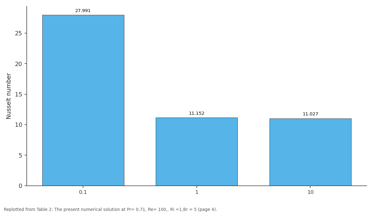
Present: 0.1 vs 1 vs 10
Replotted from Table 2 (page 4) of the original paper. Every bar is the paper's own table value.
View source evidence ↗Figures & tables
From the original paper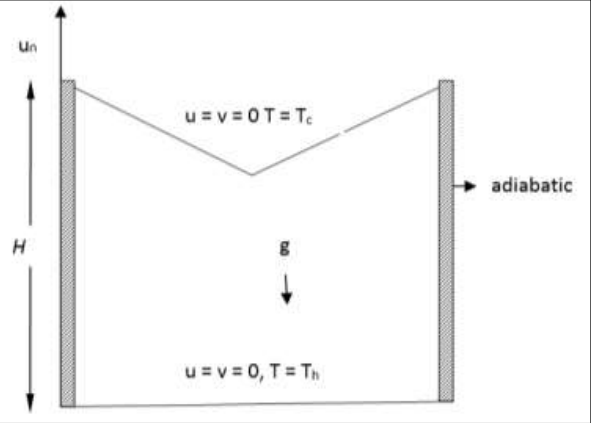 Figure 1
 Table 1
 Table 2
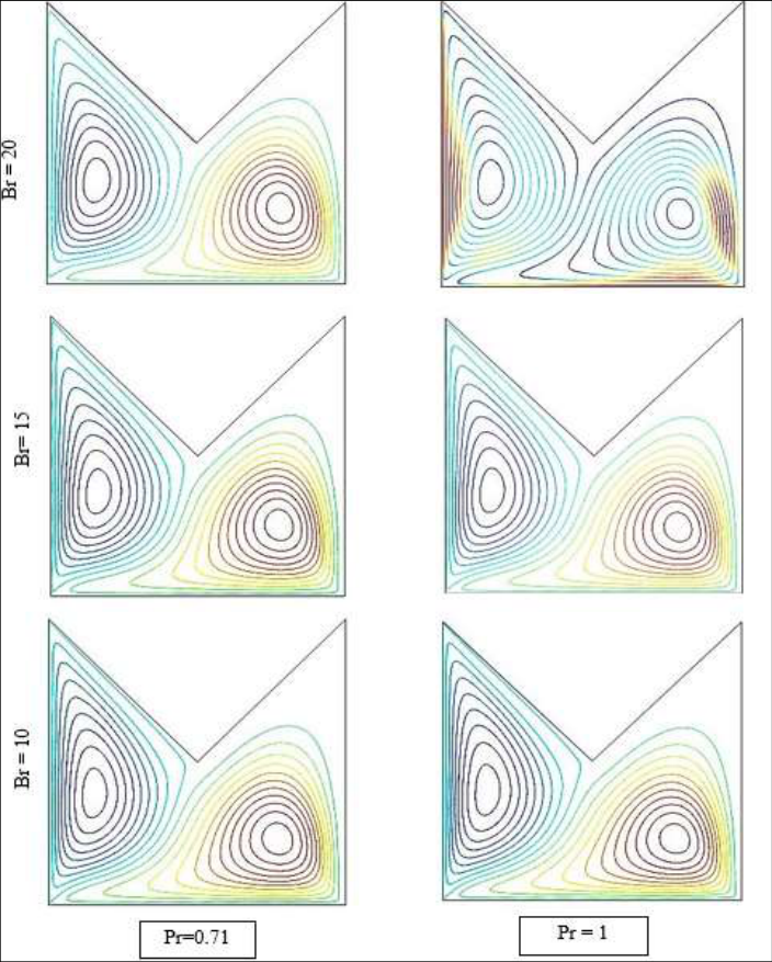 Figure 2
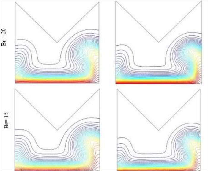 Figure 2
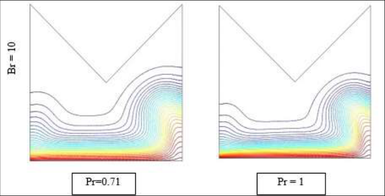 Figure 3
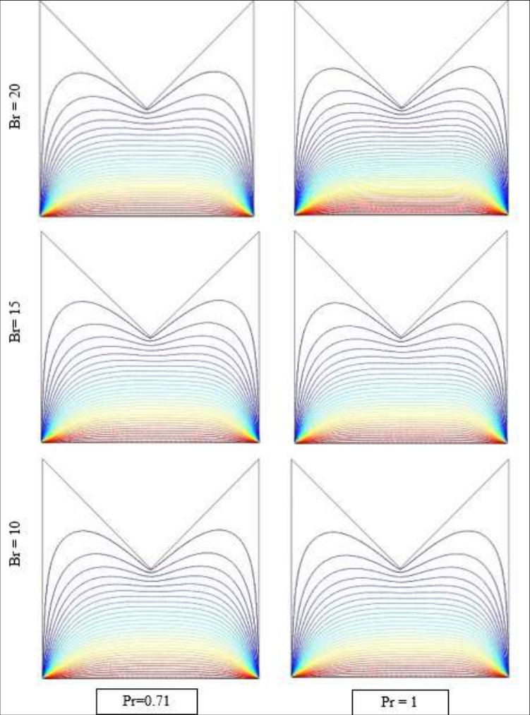 Figure 4
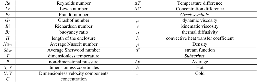 Table 2
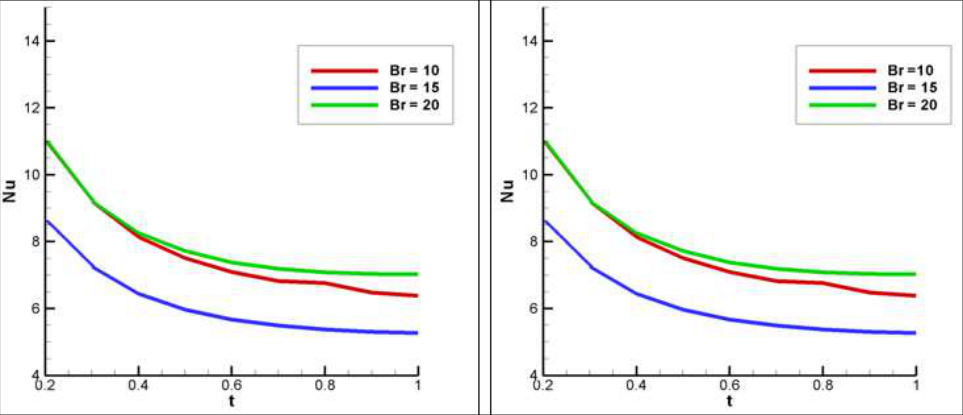 Figure 5
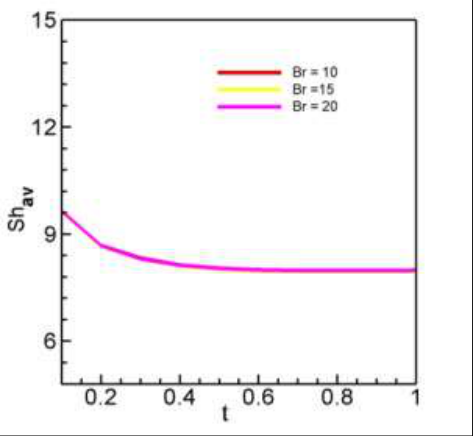 Figure 6
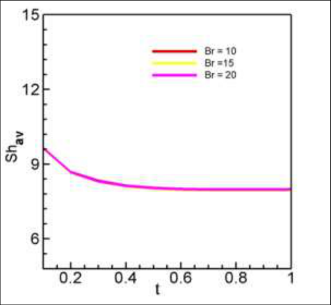 Figure 6
Introduction
Convection is a system of transferring heat through a liquid in the presence of liquid movement. Convection is classified as normal (or free) and forced convection depending on how the liquid movement is initiated. In natural convection, any liquid movement occurs by natural means such as the buoyancy effect, that is, the rise of the warm liquid and the fall of the cold liquid. During forced convection, the fluid is forced to flow over a surface or into a tube by peripheral means such as a pump. The relative path between buoyancy and forced outflow is important. In the case where the fluid is externally forced to flow in the same direction as the buoyant force, the auxiliary heat transfer method is called a combined forced and natural convection. In the case where the fluid is externally forced to flow in the opposite direction to the buoyancy force, the mode of heat transfer is termed opposing combined forced and natural convection or mixed convection. Several researchers have studied the effect of mixed convective flows in enclosures using analytical, experimental and numerical methods. Arpaci and Larsen [1] presented an analytical behavior of heat transfer with mixed convection in large cavities, whose vertical side was moving, while other vertical boundaries at different temperatures and horizontal boundaries were constant. They showed that in this particular case, the forced and buoyancy parts of the problem can be individually solved and combined to achieve the general mixed convection problem. The mixed heat load in a separate rectangular container was partially calculated by Hsu et al. [2] . Simulations have been completed for a wide range of Reynolds and Grashoff numbers. They noted that the average number of Nusselt and the temperature of the dimensional surface depend on the location and height of the separator. Mixed convection in an inclined channel was introduced by Choi and Ortega [3] . It has also been shown that the best heat transfer presentation is experimental when the duct is in a vertical position. Tai Gingras et al. [4] numerically gained the problem of time-variable synchronization is acquired in separate heating elements in forced convection of the minimum thermal resistance of laminar and fully developed flow. They proved that the activation phase and position of each heater can greatly reduce the overall thermal resistance.
Roychowdhury et al. [5] analyzed the convective flux and heat transfer features of a heated cylinder placed in a square container with varied thermal limit conditions. Dong and Li [6] considered a mixed effect of normal convection and delivery in a complex container. They observed the effects of physical character, geometry, and Rayleigh number on the heat transfer of the area concerned as a whole. They finally concluded that the flux and heat transfer increased with increasing thermal conductivity in the solid region and besides, they also affected the total flux and heat transfer significantly due to the geometry and Rayleigh number. Cheng and Liu [7] performed a numerical simulation to verify the effects of the angle of inclination, Richardson number and aspect ratio on the flow of the structure and heat transfer in a two-dimensional cavity filled with air, where the flow was performed by the shear force produced by a cooled top cover moving with the buoyancy flow of a wall Bottom heating. Ching et al. [8] measured the temperature of mixed convection and mass transfer in an upright triangular container using the finite element method. Rahman et al. [9] studied the effect of corrugated bottom on a triangular enclosure for a double diffusive buoyancy induced flow. Form of the enclosure plays a vital role in convection, while the form depends on practical application. Different types of enclosure are studied in current years. Most of them are rectangular, square, triangular, trapezoidal enclosure. An enormous amount of research interest has been raised in its potential applications to real-world problems. The study of viscous flows surrounded by a corrugated wall is of particular interest due to its application to transpiration cooling of reentry vehicles and missile booster, cross hatching on traction surfaces and film vaporization in combustion chambers. In light of these applications, Vajravelu [10] studied the combined free and forced convection in hydromagnetic flows in a vertical wavy channel with traveling thermal waves. Cho et al. [11] studied the problem of linear stability of static two-dimensional flow in corrugated-walled channels. Extensive literature surveys on the topic of porous media can be found in the most recent books [12][13][14][15][16] considered with hydrodynamic flow in the vertical wavy channel path. The main purpose of this study is to examine the mixed convection heat and mass transfer in case of supporting flow and effects moving wall cavity for different buoyancy ratio number "M" shaped closed square enclosure which is not taken into account in above literature. Here, the governing parameters are the Reynolds number, Re (=100), Lewis number, Le (= 0.1), buoyancy ratio, Br (=10, 15, 20) and Richardson number, Ri (= 1). for Prandtl number Pr=0.71 and for Pr = 1. The numerical results obtained in this study are presented in terms of streamlines, isoconcentration and average Nusselt number at the heated wall and discussed in details, with conclusions last of all.
Physical Configuration and Mathematical Formulation
We considered a two-dimensional (2-D) square enclosure of length H filled with incompressible fluid saturated with boundary conditions (Fig. 1). As seen from the schematic view, the top wavy wall is cold at temperature T c and the bottom wall is heated which is kept at heat T h , maintaining T h >T c . The remaining parts of the left0020and right walls are adiabatic and left wall is also a moving wall. The fluid is considered as Newtonian and the fluid properties are assumed constant. According to aforesaid assumptions, the governing equations for steady 2-D mixed convection flow in an enclosure using conservation of mass, momentum, energy and concentration, can be written with the following dimensionless forms:
Where, the transformed initial and boundary conditions are: t = 0, Entire domain:
where N is the non-dimensional distances either along X or Y direction acting normal to the surface. The governing equations, initial and boundary conditions are transformed into dimensionless forms using the following dimensionless variables as:
The variables have their usual sense in fluid mechanics and heat transfer as listed in the nomenclature. It can be seen from the above Eqs. ( 2)-( 5), five parameters that preside over this problem are the Reynolds number (Re), Prandtl number (Pr), Richardson number (Ri), Lewis number (Le) and buoyancy ratio (Br), which are defined respectively as 22 0
The non-dimensional stream function is defined as:
Numerical Implementation
The nonlinear governing partial differential equations, i. e, mass, momentum, energy and concentration equations are transferred into a system of integral equations by using the Galerkin weighted residual finite element method. Details of the method are described in Zienkiewicz & Taylor [17] . The integration involved in each term of these equations is performed by using Gauss's quadrature method. Newton's method is used to modify the non-linear algebraic equations into linear equations with the help of the boundary conditions. Then finally we use Triangular Factorization method to solve these linear equations. The convergence of solutions is assumed when the relative error for each variable between consecutive iterations is recorded below the convergence criterion ε such that |Γm + 1 -Γm| ≤ 10 -4 , where m is number of iteration and Γ is the general dependent variable
Grid sensitivity check
Initially a grid sensitivity check is conducted to choose the proper grid for the numerical prediction. Five different types of grid are considered for the grid refinement analysis: 42379 nodes, 3804elements; 45109 nodes, 4064 elements; 48219 nodes, 4770 elements; 53950nodes, 4906 elements and 91750 nodes, 8506 elements. The deviations among the results are very little as shown in Table-1. Therefore, the results of grid with 4064 elements are selected throughout the simulation.
Code Validation
The computational results are compared with the literature Ching et al. [8] for validation of the present numerical code. The physical problem studied by Ching et al. [8] was a lid-driven triangular enclosure. The length and height of the enclosures are depicted by L and H, respectively. The vertical wall of the cavity is allowed to moves upward or downward direction in its own plane at a constant velocity V 0 and to be kept at insulated. In addition, the bottom and inclined walls are maintained at uniform but different temperatures and concentrations. The calculated average Nusselt numbers are shown in Table 4.1. It can be seen from the figures that the present results and those reported in Ching et al. [8] are in excellent agreement. This validation boosts the confidence in the numerical outcome of the present work.
Comparison of average Nusselt number between the present numerical solution and that of Ching et al. [8] at Pr= 0.71, Re= 100,. Ri =1,Br = 5
Result and Discussion
A mathematical examination has been performed to obtain mixed convection heat and mass transfer in an enclosure with upward lid-driven cavity from the left vertical wall. Finite element method was used to solve governing equations of momentum, energy mass and concentration balance. Calculations are done for the Reynolds number, Re (=100), Lewis number, Le (= 0.1), buoyancy ratio, Br (=10,15, 20) and Richardson number, Ri (= 1). Fig. 2 shows the streamline for Pr=0.71 and for Pr = 1 and along with special buoyancy ratios. By reason of opposing flow to the buoyancy force the buoyancy ratio becomes insignificant on flow pattern. The flow becomes static at the right upper corner. A clockwise and anticlockwise circulation cells are formed, and here left one is clockwise and right one is anticlockwise. For both cases left side cells are covered full entire enclosure but left side cell is not able to do so. The development of circulating cell is for the reason that of the mixing of the fluid due to buoyancy driven and convective currents. The colour of cells changes with increasing of the buoyancy ratio. Isotherms help to visualize and interpret the horizontal temperature distribution of an area by viewing patterns of temperature on an enclosure. Constructing a map of isotherms is a straightforward step in temperature data analysis, and the process in general is called contouring. Isotherms are always smoothing, labeled with the values, and mostly parallel to each other. As seen from the Fig. 3 that temperature of the bottom wall of the enclosure has been higher as that of the vertical walls are adiabatic. For Pr= 0.71, isotherms near the bottom wall are almost parallel to the horizontal wall. Wavy of the curl of isotherms changes with way of moving lid and buoyancy ratio is an effective parameter on isotherms as seen from Fig. 3. Isotherm lines according to this issue are presented in Fig. 3 for the different buoyancy ratio numbers. Isotherms become the more effective on heated wall due to strong convection. For Pr= 1, red colored isotherms lines near the bottom wall are becoming more visible due to increasing buoyancy ratio number within the enclosure. More to add, in both case isotherm lines are in wavy shape which shows a significant effect within the entire domain due to lid driven wall. Isoconcentration plots are illustrated in Fig. 4, for Br=10,15 and 20 at Pr = 0.71 and Pr = 1 respectively. They are presented for two belongings according to moving lid direction. Distribution of isoconcentration resembles to isotherms at the same constant number. As seen from the Fig. 4, buoyancy ratio becomes not worth mentioning for each case. For both cases, a curvy shaped distribution is observed from the heated wall to cold wall. Therefore, all the times two colors isoconcentration plots are appeared intensely. At heated wall plots are in a straight line. Then next, it's becoming curvy near to upper wall. This interesting change occur due to stronger effect of the high concentration at the bottom. Average Nusselt number is presented for the abovementioned cases, different buoyancy ratio numbers in Fig. 5. As seen from Fig. 5, higher heat transfer is formed similar type for that of both cases. For higher values of buoyancy ratio numbers (Br =20), heat transfer becomes higher for initial stage after then that decreases with respect to time. Variation of Sherwood number with the different values buoyancy ratio number is shown in Fig. 6. As seen from figure, mass transfer is formed and value is also increased with increasing of the buoyancy ratio due to incoming of more energy into the system. However, variations of Sherwood number for different values buoyancy ratio number are almost in similar form. No significant change has been seen for variation of buoyancy ratio number.
Conclusion
A mathematical examination has been performed for mixed convection heat and mass transfer in a lid-driven enclosure: heated from the bottom and cooled from upper wall. Some significant discoveries can be recorded as follows: Moving lid driven wall is the most important parameters on flow, heat and mass transfer inside the enclosure. Effects of the buoyancy ratio on flow, heat and mass transfer become insignificant for lower values. Also, for higher values of buoyancy ratio affects the flow field. Average mass transfer rate is almost same for different values of buoyancy ratio number.
Figures and tables from the paper
| No.of elements(Nodes) | 3804(42379) | 4064(45109) | 4770(48219) | 4906(53950) | 8506(91750) |
|---|---|---|---|---|---|
| Ave. Nu | 6.699544 | 6.699605 | 6.690708 | 6.683317 | 6.694791 |
| Ave. Sh | 7.957793 | 7.959801 | 7.95202 | 7.957217 | 7.963081 |
Table text extracted from the original PDF; superscript letters are shown inline. The original table image is below.
View original table image
| Ri | Present | Ching et al. [8] |
|---|---|---|
| 0.1 | 27.991 | 28.653 |
| 1 | 11.152 | 12.231 |
| 10 | 11.027 | 11.569 |
Table text extracted from the original PDF; superscript letters are shown inline. The original table image is below.
View original table image
| Re | Reynolds number | ∆T | Temperature difference |
|---|---|---|---|
| Le | Lewis number | ∆C | Concentration difference |
| Pr | Prandtl number | Greek symbols | |
| Gr | Grashof number | μ | dynamic viscosity |
| Ri | Richardson number | ν | kinematic viscosity |
| Br | buoyancy ratio | | thermal diffusivity |
| H | length of the enclosure | h | convective heat transfer coefficient |
| Nuav | Average Nusselt number | | Density |
| Shav | Average Sherwood number | Ψ | stream function |
| T | dimensionless temperature | Subscripts | |
| P | non-dimensional pressure | Av | Average |
| X, Y | dimensionless coordinates | h | Hot |
| U, V | Dimensionless velocity components | c | Cold |
| C | concentration |
Table text extracted from the original PDF; superscript letters are shown inline. The original table image is below.
View original table image
References
17 in the original paper- Arpaci VS, Larsen PS. Convection Heat Transfer. Prentice-Hall 1984, 90.
- Hsu TH, Hsu PT, How SP. Mixed convection in a partially divided rectangular enclosure. Numer. Heat Transfer, Part A 1997;31:655-683.
- Choi CY, Ortega A. Mixed convection in an inclined channel with a discrete heat source, Int. J. Heat Mass Transfer 1993;36(2):3119-3134.
- Tye-Gingras M, Gosselin L, Da Silva AK. Synchronizing time-varying discrete heating elements in forced convection for minimal thermal resistance. Int. J. Heat Mass Transfer 2010;53:4917-926.
- Roychowdhury DG, Das SK, Sundararajan TS. Numerical simulation of natural convection heat transfer and fluid flow around a heated cylinder inside an enclosure. Int. J. Heat Mass Transfer 2002;38:565-576.
- Dong SF, Li YT. Conjugate of natural convection and conduction in a complicated enclosure. Int. J. Heat Mass Transfer 2004;47:2233-2239.
- Cheng TS, Liu WH. Effects of cavity inclination on mixed convection heat transfer in a lid-driven cavity flows. Comput. Fluids 2014;100:108-122.
- Ching YC, Öztop HF, Rahman MM, Islam MR, Ahsan A. Finite element simulation of mixed convection heat and mass transfer in a right triangular enclosure. Int. J. Heat Mass Transf 2012;39:689-696.
- Rahman MM, Saidur R, Mekhilef S, Uddin MB, Ahsan A. Double-diffusive buoyancy induced flow in a triangular enclosure with corrugated bottom wall: Effects of geometrical parameters. Int. Comm. Heat Mass Transfer 2013;45:64-74.
- Vajravelu K. Combined free and forced convection in hydromagnetic flows in Vertical wavy channels, with traveling thermal waves. Int. J. Engg. Sci 1989;27:289-300.
- Cho KJ, Kim MU, Shin HD. Linear stability of two-dimensional steady flow in wavy-walled channels. Fluid Dynamics Res 1998;23:349-370.
- Nield A, Bejan A. Convection in Porous Media. Springer, Newyork 1999.
- Vafai K. Hand Book of Porous Media. vol. II, Marcel Dekker, Newyork 2002.
- Pop I, Ingham DB. Convective Heat Transfer: Computational and Mathematical of Modeling Viscous Fluids and Porous Media. Pergamon, Oxford 2001.
- Bejan A, Kraus AD. Heat Transfer Handbook. Wiley, Newyork 2003.
- Guria M, Jana RN. Hydrodynamic flows through vertical wavy channel with traveling thermal waves embedded in porous medium. Int. J. Appl. Mech. Engg 2006;3:609-621.
- Zienkiewicz OC, Taylor RL. The Finite Element Method Solid and Structural Mechanics, Sixth Ed., McGraw-Hill 2005.