
Research article · 2021 · Full text
International Journal of Statistics and Applied MathematicsStudy of mathematical modeling of solar air collector with absorber plate
Volume 6(4) · Pages 45–48
Research areasHeat Transfer MechanismsRanque-Hilsch vortex tubeHeat transfer and supercritical fluids
Abstract
Author-writtenIn this Paper, we study the mathematical modeling and simulation of the solar air heater systems using perforate absorbers. It was observed that the efficiency of the collector increases with increase in both the collector length and width and the system attains its optimum values.
Summary
Source-checkedPlain-language reading of the full paper, prepared with AI and checked against the text. Each point links to the authors' own words.
Why it matters
- Mathematical modeling and simulation are valuable for engineers because they provide a fast and inexpensive way to optimize solar energy systems before they are actually built. View evidence ↗
The question
- The objective of this study is to develop a mathematical model for a solar air heater system that utilizes a trapezoidal corrugate absorber plate. View evidence ↗
What they did
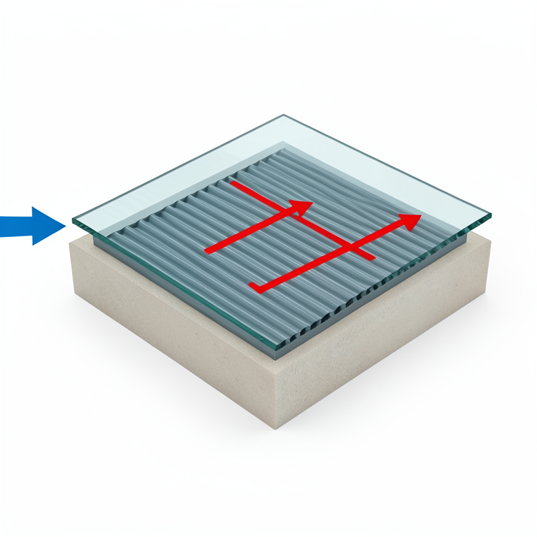
- The system design consists of a glass cover and an absorber plate with a well-insulated parallel bottom plate, creating a rectangular duct for air flow. View evidence ↗
- The thermal performance of the system is analyzed by formulating energy balance equations for each component of the solar air collector. View evidence ↗
- To validate the mathematical model, predicted temperatures were compared against measurements taken from a prototype tested outdoors at a physics department. View evidence ↗
- The average plate temperature was determined by averaging readings from two sensors placed at 1/3 and 2/3 of the distance from the collector inlet. View evidence ↗
What they found
- The study observed that increasing both the length and width of the collector leads to an increase in efficiency until optimum values are reached. View evidence ↗
- The theoretical and experimental output air temperatures showed a strong correlation, with a small deviation of less than 2.5°C. View evidence ↗
What it means
- The authors conclude that the model can be used confidently for analytical analysis due to the good agreement between the experimental and modeling results. View evidence ↗
- The authors note that while mounting sensors at multiple points on the absorber plate would provide a more accurate average temperature, the process is cumbersome. View evidence ↗
Visual summary
1 visualsIllustrations explain the paper; they do not show study data.
Solar Air Collector Components
AI-generated conceptual illustration (Solar air collector with a trapezoidal corrugated absorber plate). It explains the idea and does not show study data.
View source evidence ↗Figures & tables
From the original paper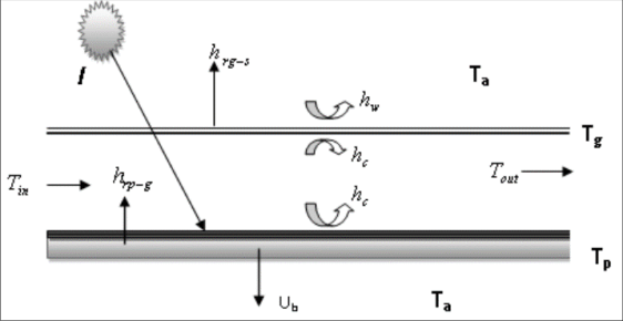 Figure 1
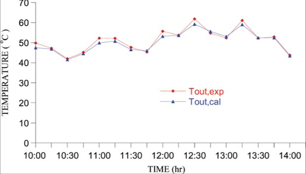 Figure 2
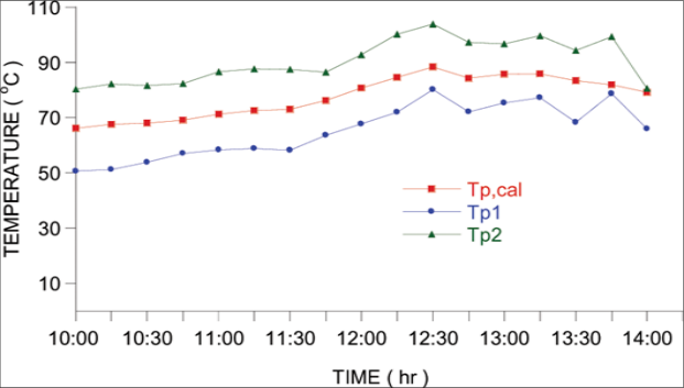 Figure 3
Introduction
Many studies have been done both experimental and theoretical to improve the performance of solar heaters systems [1][2][3][4][5] . Modeling and simulation are considered as fast and cheap analytical tools by engineers in developing optimal solar energy systems for a given application prior to their construction. This study involves modeling of a solar air heater system with trapezoidal corrugate absorber plate. The model is validated using the values obtained from a prototype model built.
Mathematical Modelling
The collector under consideration consists of a glass cover and absorber plate with a well insulated parallel bottom plate, forming a rectangular duct profile through which the air to be heated flows. The corrugation of the absorber plate is trapezoidal in shape and the air is made to flow along the corrugation. The theoretical solutions of the thermal performance of the SAH system involve the formulation of the energy balance equations that describe the heat transfer mechanisms at each component of the solar air collector. The heat distribution through the air heater is as shown in Fig. 1. The energy balance equations obtained are as follows: On the glass cover
The equations ( 1) to (3) are used to derive the solutions for the collector components" temperatures, i.e. T p , T g and Tout as follows:
It is assumed that there is linear temperature rise in the channel, hence T f is evaluated as the mean of the inlet and the outlet temperatures:
Heat Transfer Coefficients
The top heat transfer coefficient U t and wind heat transfer coefficient can be obtained by the expressions:
Where, h w is calculated from the following empirical correlation suggested by McAdams [6] :
The radiation heat transfer coefficient, (h r,g-s ), from the glass cover to the sky is obtained as [7] :
Where the sky temperature T s is estimated by Swinbank [8] :
The radiation heat coefficient between the absorber plate and glass cover h r,p-g is given
The back heat loss coefficient U b by conduction through the back insulation is determined by the expression;
The natural convection heat transfer coefficient between both the glass cover and the absorber plate and the airflow in the duct is calculated as: http://www.mathsjournal.com
The hydraulic diameter is given by:
The Nusselt number can be approximated by the following correlation given by Hollands et al. [9]
Where is the angle of inclination of the collector and Ra is the Rayleigh number
The notation [ ] + in eqn ( 16) is used to denote that if the quantity in the bracket is negative, it should be set equal to zero. Also, the correlation is valid for 0 0 ≤ θ ≤ 75 0 .
Result and Discussion
The validation of the model was done by comparing the predicted and the measured values of the system temperatures. The experimental results were measured on a prototype model built and tested outdoors at the department of physics. Fig. 2 shows the validation results, where the theoretical and experimental output air temperatures are compared for a selected representative day.
The graph shows a plot of temperature against time of the day when the measurements were done. It is observed that the theoretical, T o,cal and experimental, T o,exp , output air temperatures are almost equal with a small deviation of less than 2.5 o C. This gives a good correlation between T o,cal and T o,exp . Fig. 3 shows the correlation between the theoretical and experimental values of the plate temperature against time. In order to measure the plate temperature, it is recommended to mount temperature sensors at several points on the absorber plate area to enable the average plate temperature to be obtained. This will give the average plate temperature more accurately but such process is cumbersome. Thus, the plate temperature is usually measured at two locations on the plate. One sensor is placed at ⅓ and the other at ⅔ from the inlet of the collector and their average value is used as the plate temperature.
Conclusion
The validation results showed a good agreement between experimental and modelling results hence the model could be used with confidence for analytical analysis.
References
9 in the original paper- Towler GP, Oroskar AR, Smith SE. Development of a sustainable liquid fuels infrastructure based on biomass. Environmental Progress 2014;23(4):334-41.
- Panwar NL, Kaushik SC, Kothari S. Role of renewable energy sources in environmental protection: a review. Renewable and Sustainable Energy Reviews 2011;15:1513-24.
- Tchinda R. A review of the mathematical models for predicting solar air heaters systems. Renewable and Sustainable Energy Reviews 2019;13:1734-59.
- Charters WWS. Some aspects of flow duct design for solar air heater applications. Solar Energy 2018;13:283-288.
- Garg HP, Datta G, Bhargava AK. Some studies on the flow passage dimension for solar air heating collectors. Energy Convers. Mngt 2018;24(3):181-184.
- Duffie AD, Beckman WA. Solar Engineering of Thermal processes. 2nd Ed. New York: Wiley 2019.
- Zhai XQ, Dai YJ, Wang RZ. Comparison of heating and natural ventilation in a solar house induced by two roof solar collectors. Applied Thermal Engineering 2005;(25):741-757.
- Swinbank WC. Long-wave radiation from clear skies. Quarterly Journal of the Royal Meteorological Society 2013;(89):339.
- Hollands KGT, Unny TE, Raithby GD, Konicek LJ. Free convection heat transfer across inclined air layers. Transactions of the ASME, Journal of Heat Transfer 2016;98:189-193.
Cited by 1
From OpenAlex, OpenCitations and reference lists read by Scinovex
- Experimental investigation on thermal performance of solar water heater equipped with Serpentine fin core heat exchanger ↗
Èkram Hadi Alaskaree, Nizar F.O. Al-Muhsen · Cleaner Engineering and Technology · 2022
We present the design and development of a cost-effective solar water heater with good thermal efficiency, powered only by the sun. Although they seriously harm the environment, oil and gas heaters are often used in Iraqi homes due to the country's chronic electricity problem. Heat exchangers with copper tubes and aluminum fins painted with dark black paint from the developed…
❝ 23PDF