Scinovex

Research article · 2018 · Full text

International Journal of Statistics and Applied Mathematics

A numerical study of mixed convection in a lid-driven porous square cavity with internal elliptic block and linearly heated side walls

M. Jahirul Haque MunshiMA AlimMahtab U. Ahmmed

Volume 3(3) · Pages 191–202

Research areasNanofluid Flow and Heat TransferHeat and Mass Transfer in Porous MediaFluid Dynamics and Turbulent Flows

↓ Read full-text PDF0 citations

Abstract

Author-written

The present work is a numerical investigation of mixed convection in a lid-driven porous square cavity with internal elliptic block and linearly heated side walls with Prandtl number of 0.7. The left and right walls of the cavity were linearly heated while the top and bottom walls were maintained at constant temperatures with the top surface being the cold wall and bottom surface being the hot wall. In the double-lid cavity configuration, the top wall moved to the right while the bottom wall moved to the left at the same constant speed. The magnetic field of strength B is applied parallel to x-axis. Finite element method was employed to solve the dimensionless governing equations of continuity, momentum and energy of the problem. Using our developed code, a parametric study was performed, and the effect of the Darcy number, Grashof number, and Reynolds number on the fluid flow and heat transfer inside the square enclosure were investigated. The isotherms are also almost symmetric at small Re with Gr (Gr = 105) and Da (Da = 10-3) and natural convection is found to be dominant whereas the isotherms are compressed near the left and bottom walls at higher Re for linearly heated side walls. Results are presented in the form of streamlines and isotherms plots as well as the variation of the maximum temperature and Nusselt numbers under different conditions. The numerical results indicate the strong influence of the mentioned parameters on the flow structure and heat transfer as well as average Nusselt number. An optimum combination of the governing parameters would result in higher heat transfer.

Summary

Source-checked

Plain-language reading of the full paper, prepared with AI and checked against the text. Each point links to the authors' own words.

  1. Why it matters

    • Mixed convection in lid-driven enclosures is important for various engineering applications, including the cooling of electronic equipment and heat exchangers. View evidence ↗

      Why it matters

      Mixed convection in lid-driven enclosures is important for various engineering applications, including the cooling of electronic equipment and heat exchangers.

      In the paper's own words

      “A mixed convection problem with lid-driven flows within an enclosure finds a wide range of applications in various fields of engineering and science, such as cooling of electronic equipments, heat exchangers, building ventilation, cooling processes, and heat exchangers.”

      Page 1

      Found in: Introduction

      Read it in the full textOpen PDF at page 1 ↗
    • Studying fluid flow and heat transfer in porous media is critical for industrial processes like filtration and solar collectors. View evidence ↗

      Why it matters

      Studying fluid flow and heat transfer in porous media is critical for industrial processes like filtration and solar collectors.

      In the paper's own words

      “Heat transfer and fluid flow in porous media filled enclosures or channels have important engineering applications such as filtration, separation processes in chemical industries, solar collectors, heat exchangers, etc.”

      Page 1

      Found in: Introduction

      Read it in the full textOpen PDF at page 1 ↗
  2. The question

    • The study aims to fill a gap in research regarding mixed convection in a lid-driven porous square cavity that contains an internal elliptic block and linearly heated side walls. View evidence ↗

      The question

      The study aims to fill a gap in research regarding mixed convection in a lid-driven porous square cavity that contains an internal elliptic block and linearly heated side walls.

      In the paper's own words

      “it appears that very little work was reported on numerical investigation of mixed convection in a lid-driven porous square cavity with internal elliptic block and linearly heated side walls.”

      Page 2

      Found in: Gr

      Read it in the full textOpen PDF at page 2 ↗
  3. What they did

    • The researchers used the finite element method to solve the governing equations for continuity, momentum, and energy. View evidence ↗

      What they did

      The researchers used the finite element method to solve the governing equations for continuity, momentum, and energy.

      In the paper's own words

      “Finite element method was employed to solve the dimensionless governing equations of continuity, momentum and energy of the problem.”

      Page 1

      Found in: Dimensional Analysis

      Read it in the full textOpen PDF at page 1 ↗
    • The experimental setup involved a cavity with linearly heated side walls, a constant-temperature cold top wall, and a constant-temperature hot bottom wall. View evidence ↗

      What they did

      The experimental setup involved a cavity with linearly heated side walls, a constant-temperature cold top wall, and a constant-temperature hot bottom wall.

      In the paper's own words

      “The left and right walls of the cavity were linearly heated while the top and bottom walls were maintained at constant temperatures with the top surface being the cold wall and bottom surface being the hot wall.”

      Page 1

      Found in: Conclusions

      Read it in the full textOpen PDF at page 1 ↗
    • The cavity used a double-lid configuration where the top and bottom walls moved in opposite directions at the same constant speed. View evidence ↗

      What they did

      The cavity used a double-lid configuration where the top and bottom walls moved in opposite directions at the same constant speed.

      In the paper's own words

      “In the double-lid cavity configuration, the top wall moved to the right while the bottom wall moved to the left at the same constant speed.”

      Page 1

      Found in: Conclusions

      Read it in the full textOpen PDF at page 1 ↗
    • The study investigated how the Darcy number, Grashof number, and Reynolds number affect heat transfer and fluid flow. View evidence ↗

      What they did

      The study investigated how the Darcy number, Grashof number, and Reynolds number affect heat transfer and fluid flow.

      In the paper's own words

      “a parametric study was performed, and the effect of the Darcy number, Grashof number, and Reynolds number on the fluid flow and heat transfer inside the square enclosure were investigated.”

      Page 1

      Found in: Conclusions

      Read it in the full textOpen PDF at page 1 ↗
  4. What they found

    • Increasing the Grashof number to 10^5 increases buoyancy strength, creating two elliptic-shaped eyes in the cavity and increasing flow strength at the right wall. View evidence ↗

      What they found

      Increasing the Grashof number to 10^5 increases buoyancy strength, creating two elliptic-shaped eyes in the cavity and increasing flow strength at the right wall.

      In the paper's own words

      “For higher Grashof number increases to 10 [5], the strength of the buoyancy increases and two elliptic shape eyes inside the cavity and also flow strength increases in the right wall.”

      Page 4

      Found in: Effect of Grashof number

      Read it in the full textOpen PDF at page 4 ↗
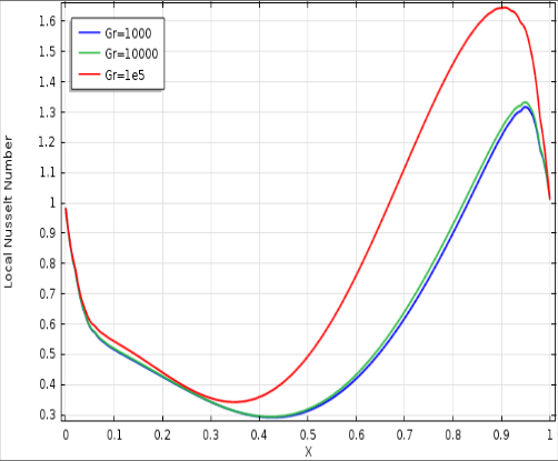
    • The maximum and minimum values of the local Nusselt number increase as the Grashof number increases. View evidence ↗

      What they found

      The maximum and minimum values of the local Nusselt number increase as the Grashof number increases.

      In the paper's own words

      “the maximum and minimum value of local Nusselt number increasing with increasing the Grashof number.”

      Page 5

      Found in: Gr

      Read it in the full textOpen PDF at page 5 ↗
    • An increase in the Darcy number causes isotherms to condense at the left and right walls, indicating an increase in convective heat transfer. View evidence ↗

      What they found

      An increase in the Darcy number causes isotherms to condense at the left and right walls, indicating an increase in convective heat transfer.

      In the paper's own words

      “Darcy number increasing isotherms condense left and right wall which means increasing heat transfer through convection.”

      Page 6

      Found in: Conclusions

      Read it in the full textOpen PDF at page 6 ↗
    • As the Darcy number increases, mixed convection is suppressed, and heat transfer becomes primarily conductive. View evidence ↗

      What they found

      As the Darcy number increases, mixed convection is suppressed, and heat transfer becomes primarily conductive.

      In the paper's own words

      “with increase in Darcy number, mixed convection is suppressed and heat transfer occurs mainly through conduction.”

      Page 6

      Found in: Introduction

      Read it in the full textOpen PDF at page 6 ↗
    • In Case I, the average Nusselt number decreases as the Darcy number increases. View evidence ↗

      What they found

      In Case I, the average Nusselt number decreases as the Darcy number increases.

      In the paper's own words

      “the average Nusselt number decreases with increasing Darcy number.”

      Page 10

      Found in: Gr

      Read it in the full textOpen PDF at page 10 ↗
    • In Case II, the average Nusselt number increases as the Grashof number increases. View evidence ↗

      What they found

      In Case II, the average Nusselt number increases as the Grashof number increases.

      In the paper's own words

      “the average Nusselt number increases with increasing Grashof number.”

      Page 10

      Found in: Gr

      Read it in the full textOpen PDF at page 10 ↗
  5. What it means

    • The authors conclude that achieving higher heat transfer requires an optimal combination of the governing parameters. View evidence ↗

      What it means

      The authors conclude that achieving higher heat transfer requires an optimal combination of the governing parameters.

      In the paper's own words

      “An optimum combination of the governing parameters would result in higher heat transfer.”

      Page 1

      Found in: Conclusions

      Read it in the full textOpen PDF at page 1 ↗
    • High Reynolds numbers enhance the lid-driven effect, while low Reynolds numbers increase the influence of the heat source on flow and heat characteristics. View evidence ↗

      What it means

      High Reynolds numbers enhance the lid-driven effect, while low Reynolds numbers increase the influence of the heat source on flow and heat characteristics.

      In the paper's own words

      “The large values of Reynolds number lead to increase the lid-driven effect whereas the small values of Reynolds number lead to increase effect of presence of the heat source on the flow and heat characteristics.”

      Page 11

      Found in: Conclusions

      Read it in the full textOpen PDF at page 11 ↗

Visual summary

3 visuals

Illustrations explain the paper; charts are replotted from the paper's own table values.

AI-generated illustration
AI-generated conceptual illustration (a porous square cavity containing a centered elliptic block). It explains the idea and does not show study data.↗ Enlarge
Cavity Configuration
AI-generated conceptual illustration (a porous square cavity containing a centered elliptic block). It explains the idea and does not show study data.

AI-generated conceptual illustration (a porous square cavity containing a centered elliptic block). It explains the idea and does not show study data.

Open full-size image ↗

Cavity Configuration

AI-generated conceptual illustration (a porous square cavity containing a centered elliptic block). It explains the idea and does not show study data.

View source evidence ↗
Replotted from source data
Replotted from a table (page 11) of the original paper. Every bar is the paper's own table value.↗ Enlarge
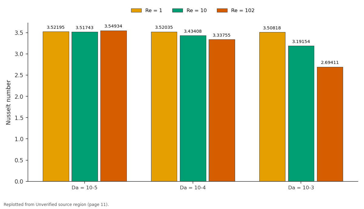
Re = 1 and Re = 10 and more: Da = 10-5 vs Da = 10-4 vs Da = 10-3
Replotted from a table (page 11) of the original paper. Every bar is the paper's own table value.

Replotted from a table (page 11) of the original paper. Every bar is the paper's own table value.

Open full-size image ↗

Re = 1 and Re = 10 and more: Da = 10-5 vs Da = 10-4 vs Da = 10-3

Replotted from a table (page 11) of the original paper. Every bar is the paper's own table value.

View source evidence ↗
Replotted from source data
Replotted from a table (page 11) of the original paper. Every bar is the paper's own table value.↗ Enlarge
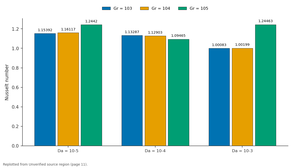
Gr = 103 and Gr = 104 and more: Da = 10-5 vs Da = 10-4 vs Da = 10-3
Replotted from a table (page 11) of the original paper. Every bar is the paper's own table value.

Replotted from a table (page 11) of the original paper. Every bar is the paper's own table value.

Open full-size image ↗

Gr = 103 and Gr = 104 and more: Da = 10-5 vs Da = 10-4 vs Da = 10-3

Replotted from a table (page 11) of the original paper. Every bar is the paper's own table value.

View source evidence ↗

Figures & tables

From the original paper
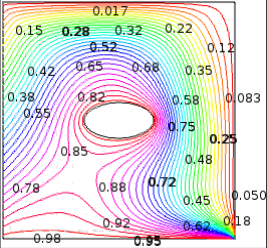
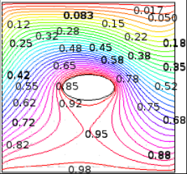
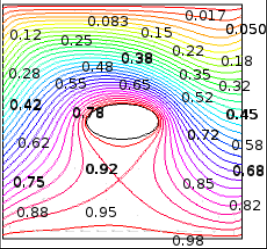
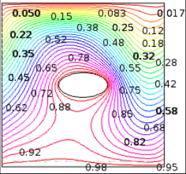
Schematic diagram of the physical systemFigure 1Page 2Schematic diagram of the physical systemFigure 1Page 2Effect of grid refinement test on average Nusselt numberFigure 2Page 4Mesh generation in a lid-driven porous square cavity with internal elliptic blockFigure 3Page 4Illustrate the streamlines involving heated bottom moving wall, linearly heated left and right wall, upper cold moving wall and ellipticFigure 4Page 5Illustrate the streamlines involving heated bottom moving wall, linearly heated left and right wall, upper cold moving wall and ellipticFigure 4Page 5Illustrate the streamlines involving heated bottom moving wall, linearly heated left and right wall, upper cold moving wall and ellipticFigure 4Page 5Illustrate the streamlines involving heated bottom moving wall, linearly heated left and right wall, upper cold moving wall and ellipticFigure 4Page 5Illustrate the streamlines involving heated bottom moving wall, linearly heated left and right wall, upper cold moving wall and ellipticFigure 4Page 5Illustrate the streamlines involving heated bottom moving wall, linearly heated left and right wall, upper cold moving wall and ellipticFigure 4Page 5Illustrate the isotherms involving heated bottom moving wall, linearly heated left and right wall, upper cold moving wall and ellipticFigure 5Page 5Illustrate the isotherms involving heated bottom moving wall, linearly heated left and right wall, upper cold moving wall and ellipticFigure 5Page 5Illustrate the isotherms involving heated bottom moving wall, linearly heated left and right wall, upper cold moving wall and ellipticFigure 5Page 5Variation of Local Nusselt number and Velocity of the square cavity with Grashof number Gr = 103 to 105.Figure 6Page 6Variation of Local Nusselt number and Velocity of the square cavity with Grashof number Gr = 103 to 105.Figure 6Page 6Streamlines and isotherms for linearly heated left walls and cold right wall with Pr = 0.7, Re = 100 and Gr = 105 for: (a) Da = 10-5; (b) DaFigure 7Page 7Streamlines and isotherms for linearly heated left walls and cold right wall with Pr = 0.7, Re = 100 and Gr = 105 for: (a) Da = 10-5; (b) DaFigure 7Page 7Streamlines and isotherms for linearly heated left walls and cold right wall with Pr = 0.7, Re = 100 and Gr = 105 for: (a) Da = 10-5; (b) DaFigure 7Page 7Streamlines and isotherms for linearly heated left walls and cold right wall with Pr = 0.7, Re = 100 and Gr = 105 for: (a) Da = 10-5; (b) DaFigure 7Page 7Streamlines and isotherms for linearly heated left walls and cold right wall with Pr = 0.7, Re = 100 and Gr = 105 for: (a) Da = 10-5; (b) DaFigure 7Page 7Streamlines and isotherms for linearly heated left walls and cold right wall with Pr = 0.7, Re = 100 and Gr = 105 for: (a) Da = 10-5; (b) DaFigure 7Page 7Isotherms for linearly heated left wall and cold right wall with Pr = 0.7, Re = 100 and Gr = 105 for: (a) Da = 10-5; (b) Da = 10-4; (c) Da =Figure 8Page 7Isotherms for linearly heated left wall and cold right wall with Pr = 0.7, Re = 100 and Gr = 105 for: (a) Da = 10-5; (b) Da = 10-4; (c) Da =Figure 8Page 7Isotherms for linearly heated left wall and cold right wall with Pr = 0.7, Re = 100 and Gr = 105 for: (a) Da = 10-5; (b) Da = 10-4; (c) Da =Figure 8Page 7Variation of temperature gradient along the right wall of the square cavity with Darcy numberFigure 9Page 8Variation of temperature gradient along the right wall of the square cavity with Darcy numberFigure 9Page 8Streamlines and isotherms for linearly heated left wall and cold right wall with Pr = 0.7, Gr = 104 and Da = 10-3 for: (a) Re = 1; (b) Re =Figure 10Page 9Streamlines and isotherms for linearly heated left wall and cold right wall with Pr = 0.7, Gr = 104 and Da = 10-3 for: (a) Re = 1; (b) Re =Figure 10Page 9Streamlines and isotherms for linearly heated left wall and cold right wall with Pr = 0.7, Gr = 104 and Da = 10-3 for: (a) Re = 1; (b) Re =Figure 10Page 9Streamlines and isotherms for linearly heated left wall and cold right wall with Pr = 0.7, Gr = 104 and Da = 10-3 for: (a) Re = 1; (b) Re =Figure 10Page 9Streamlines and isotherms for linearly heated left wall and cold right wall with Pr = 0.7, Gr = 104 and Da = 10-3 for: (a) Re = 1; (b) Re =Figure 10Page 9Streamlines and isotherms for linearly heated left wall and cold right wall with Pr = 0.7, Gr = 104 and Da = 10-3 for: (a) Re = 1; (b) Re =Figure 10Page 9Isotherms for linearly heated left wall and cold right wall with Pr = 0.7, Gr = 104 and Da = 10-3 for: (a) Re = 1; (b) Re = 10; and (c) Re =Figure 11Page 9Isotherms for linearly heated left wall and cold right wall with Pr = 0.7, Gr = 104 and Da = 10-3 for: (a) Re = 1; (b) Re = 10; and (c) Re =Figure 11Page 9Isotherms for linearly heated left wall and cold right wall with Pr = 0.7, Gr = 104 and Da = 10-3 for: (a) Re = 1; (b) Re = 10; and (c) Re =Figure 11Page 9Isotherms for linearly heated left wall and cold right wall with Pr = 0.7, Gr = 104 and Da = 10-3 for: (a) Re = 1; (b) Re = 10; and (c) Re =Figure 11Page 9Isotherms for linearly heated left wall and cold right wall with Pr = 0.7, Gr = 104 and Da = 10-3 for: (a) Re = 1; (b) Re = 10; and (c) Re =Figure 11Page 9Variation of Local Nusselt number and dimensionless temperature along the right wall of the square cavity with Reynolds numberFigure 12Page 10Variation of Local Nusselt number and dimensionless temperature along the right wall of the square cavity with Reynolds numberFigure 12Page 10Variation of the average Nusselt number along the right wall of the square cavity with different Darcy numbers and Reynolds numbersFigure 13Page 11Variation of the average Nusselt number along the right wall of the square cavity with different Darcy numbers and Reynolds numbersFigure 13Page 11Streamline and isotherms for different Grashof number Present study (a) without obstacle (b) with elliptic obstacleFigure 14Page 11Streamline and isotherms for different Grashof number Present study (a) without obstacle (b) with elliptic obstacleFigure 14Page 11
FULL TEXT Original article · reflowed for reading

Introduction

A mixed convection problem with lid-driven flows within an enclosure finds a wide range of applications in various fields of engineering and science, such as cooling of electronic equipments, heat exchangers, building ventilation, cooling processes, and heat exchangers. Heat transfer and fluid flow in porous media filled enclosures or channels have important engineering applications such as filtration, separation processes in chemical industries, solar collectors, heat exchangers, etc. Studies on thermal convection in porous media and state-of-the-art reviews are given by Ingham and Pop [1] , Bejan [2] , and Vafai [3] . The literature detailed concerning the porous media in the books by J. N. Ready [4] , O. S. Zienkieuicz et al. [5] , T. K. Bask et al. [6] , M. Sathiyamoorthy [7] . The modern technologies require through understanding of the pertinent processes involved in these fields. Considerable research work has been reported in the literature on natural convection due to combined thermal and mass buoyancy forces. Unfortunately, pure natural or pure forced convection situations seldom arise in practice. The involvement of both natural and forced convection, referred as mixed convection, in porous media has been an important topic because of its wide range of application in engineering and science. The governing non-dimensional parameter for the description of flows are Grashof number (Gr), Reynolds number (Re), Prandtl number (Pr) and Darcy number (Da). Another important non-dimensional parameter, Richardson number characterizes mixed convection flow where Gr and Re represent the strength of the natural and forced convection flow effect, respectively. The detailed literature concerning convective flow in porous media is available in the books by Nield and Bejan [8] , Ingham and Pop [9] , Ingham [10] and Bejan et al. [11] . Oztop [12] investigated numerically combined convection heat transfer and fluid flow in a partially heated porous lid-driven cavity. Volume averaged equations governing unsteady, laminar, mixed convection flow in an enclosure filled with a Darcian fluid-saturated uniform porous medium in the presence of internal heat generation is investigated by Khanafer and Chamkha [13] . Chamkha [14] also studied the mixed convection flow along a vertical permeable plate embedded in a porous medium in the presence of transverse magnetic field and non-Darcy fully developed steady laminar mixed convection flow of an electrically conducting and heat generation/ absorption fluid in a porous medium channel. Mixed convection in porous cavity has also been analyzed in presence of internal heat generation. Khanafer and Chamka [15] analyzed laminar, mixed convection flow in a Darcian fluid-saturated porous cavity in the presence of internal heat generation and they found that the flow and the heat transfer inside the cavity were strong function of Richardson number (Ri). A recent investigation of Bask et al. [16] was based on mixed convection of fluid within a cavity in presence of uniform and non-uniform bottom heating while the top plate is maintained at uniform velocity.

Nomenclatures

Nomenclatures

Gr

On the basis of the literature review, it appears that very little work was reported on numerical investigation of mixed convection in a lid-driven porous square cavity with internal elliptic block and linearly heated side walls. Thus, the obtained numerical results of the present problem are presented graphically in terms of streamlines, isotherms, velocity, dimensionless temperature, local Nusselt number and average Nusselt number for different Grashof numbers, Darcy numbers and Reynolds numbers.

Problem Formulation

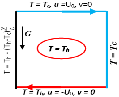
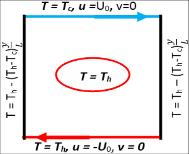
The physical model considered in the present study of mixed convection in a lid-driven porous square cavity with internal elliptic block and linearly heated side walls is shown in Fig. 1. The height and the width of the cavity are denoted by L. The heated wall denoted by T h and cold wall denoted by T c respectively. The arrangement of the moving and linearly heated has great impact on the fluid flow structures in the enclosure as follows:

Figure 1. Schematic diagram of the physical system
Schematic diagram of the physical system↗ Enlarge
Figure 1
Schematic diagram of the physical system

Schematic diagram of the physical system

Open full-size image ↗
Original paper figureSource PDF · page 2 ↗
Figure 1. Schematic diagram of the physical system
Schematic diagram of the physical system↗ Enlarge
Figure 1
Schematic diagram of the physical system

Schematic diagram of the physical system

Open full-size image ↗
Original paper figureSource PDF · page 2 ↗

Case I Case II

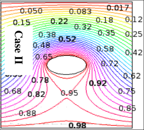
Case I. The left wall linearly heated, upper and right wall cold, lower wall and inside elliptic obstacle heated. The top lid is assumed to have a constant speed U 0 that slides in the positive direction of x-axis and lower lid is assumed to have a constant speed -U 0 that slides in the negative direction of x-axis.

Case II: The left and right wall linearly heated, upper wall cold, lower wall and inside elliptic obstacle heated. The top lid is assumed to have a constant speed U 0 that slides in the positive direction of x-axis and lower lid is assumed to have a constant speed -U 0 that slides in the negative direction of x-axis.

Governing Equations

The fluid is considered as incompressible, Newtonian and the flow is assumed to be laminar. The governing equations for steady two-dimensional natural convection flow in the porous cavity using conservation of mass, momentum and energy can be written as:

where 𝑥, 𝑦 are the distance measured along the horizontal and vertical directions, 𝑢, 𝑣 are the velocity components in the x and y directions, 𝜌 is the density, 𝑝 is the pressure, 𝜈 is the kinematic viscosity, Κ is the permeability of the porous medium, 𝑔 is the acceleration due to gravity, 𝛼 is the thermal diffusivity, 𝛽 is the volume expansion coefficient, 𝑇 is the temperature.

Boundary Conditions

The boundary conditions for the present problem are specified as follows:

Linearly heated left and right walls:

Dimensional Analysis

The governing equations for steady two-dimensional mixed convection flow in a lid-driven porous square cavity using conservation of mass, momentum and energy can be written with the following dimensionless variables or numbers: Continuity Equation

Transformed boundary conditions are:

At the cold top walls: 𝜃 = 0, 𝑈 = 1, 𝑉 = 0 At the heated bottom wall: 𝜃 = 1, 𝑈 = -1, 𝑉 = 0 Linearly heated left wall: 𝜃 = 1 -𝑌, 𝑈 = 0, 𝑉 = 0 (9) Linearly heated right wall: 𝜃 = 1 -𝑌 𝑜𝑟 0, 𝑎𝑛𝑑 𝑈 = 0, 𝑉 = 0 At the heated elliptic body: 𝑈 = 0, 𝑉 = 0, 𝜃 = 1

The following dimensionless variables and parameters have been used in Eqs. ( 5)-( 8):

Note that, thermal diffusivity (𝛼) and kinematic viscosity (𝜈) in Eq. ( 8) are defined based on local thermal equilibrium between solid and fluid within a porous control volume D. A. Nield et al. [8] where 𝛼 = . Here 𝑘 𝑒𝑓𝑓 is the effective thermal conductivity of the porous matrix, 𝜙 is the porosity, 𝐶 𝑝𝑓 is the specific heat of fluid, 𝜇 𝑓 is the viscosity of fluid and 𝜌 0 = 𝜌 is the density of fluid at 𝜃 = 0.

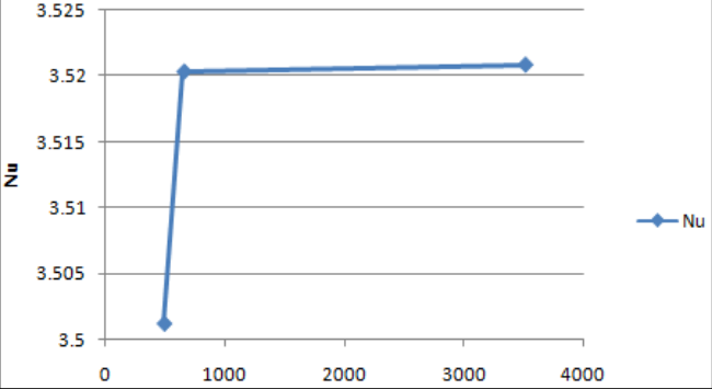
Grid Refinement Test

A grid independence test is reported with Pr = 0.

Mesh Generation

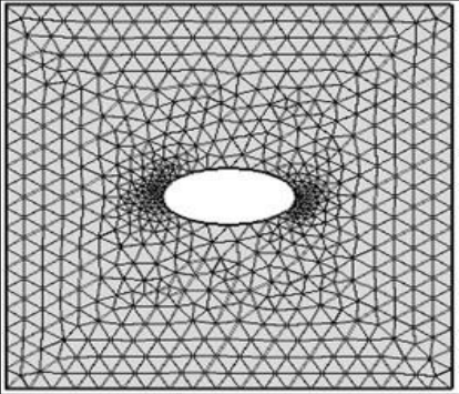
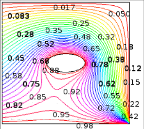
In finite element method, the mesh generation is the technique to subdivide a domain into a set of sub-domains, called finite elements, control volume etc. The discrete locations are defined by the numerical grid, at which the variables are to be calculated. The computational domains with irregular geometries by a collection of finite elements make the method a valuable practical tool for the solution of boundary value problems arising the various fields of engineering. Fig. 3 displays the finite element mesh of the present physical domain.

Figure 3. Mesh generation in a lid-driven porous square cavity with internal elliptic block
Mesh generation in a lid-driven porous square cavity with internal elliptic block↗ Enlarge
Figure 3
Mesh generation in a lid-driven porous square cavity with internal elliptic block

Mesh generation in a lid-driven porous square cavity with internal elliptic block

Open full-size image ↗
Original paper figureSource PDF · page 4 ↗

Results and Discussions

A numerical study has been performed a numerical study of mixed convection in a lid-driven porous square cavity with internal elliptic shape heated block and linearly heated side walls. The results are presented in terms of streamlines, isotherm, Local Nusselt number along the hot wall, dimensionless temperature, velocity profiles and the average Nusselt number of the hot wall.

Effect of Grashof number

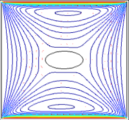
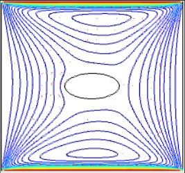
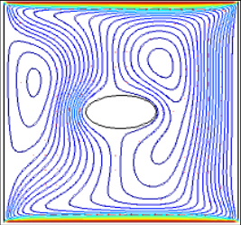
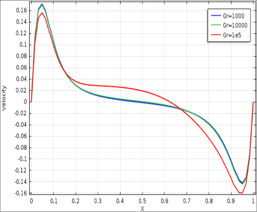
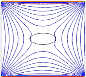
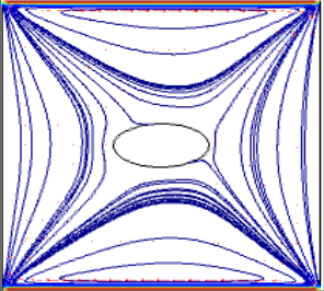
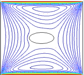
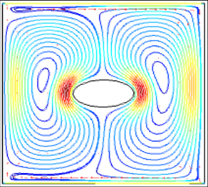
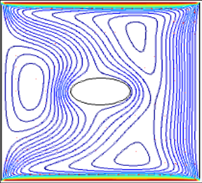
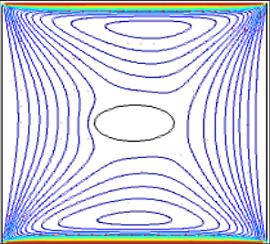
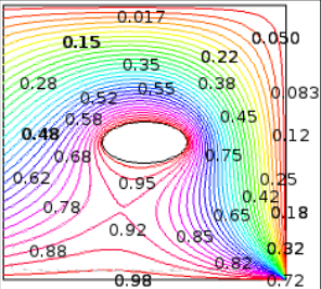
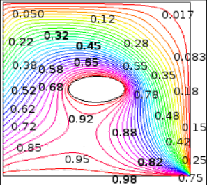
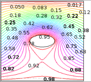
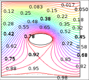
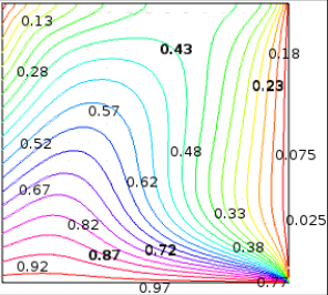
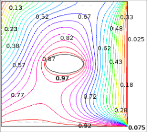
Variation of streamlines and isotherms inside the cavity with different Grashof number and Darcy number are shown in Fig. 4 and 5, respectively. As can be observed from the Fig, the strength of the buoyancy inside the cavity is significant and more fluid rise from the centre of the cavity at Gr = 10 [3] . As Gr increases to 10 [4] , the effect of natural convection increases and the strength of both primary and secondary circulations increase. For higher Grashof number increases to 10 [5] , the strength of the buoyancy increases and two elliptic shape eyes inside the cavity and also flow strength increases in the right wall. Comment to both cases, the flowing flow due to moving lid becomes very strong due to high Grashof number. The natural convection becomes dominant as the lid-driven flow and the strength of both the circulations are increased. Due to uniform heating of the bottom wall and linearly heated side walls, fluid rise from the upper and lower walls of the cavity forming two almost symmetric rolls with clockwise rotations inside the cavity.

Figure 4. Illustrate the streamlines involving heated bottom moving wall, linearly heated left and right wall, upper cold moving wall and elliptic
Illustrate the streamlines involving heated bottom moving wall, linearly heated left and right wall, upper cold moving wall and elliptic↗ Enlarge
Figure 4
Illustrate the streamlines involving heated bottom moving wall, linearly heated left and right wall, upper cold moving wall and elliptic

Illustrate the streamlines involving heated bottom moving wall, linearly heated left and right wall, upper cold moving wall and elliptic

Open full-size image ↗
Original paper figureSource PDF · page 5 ↗

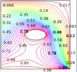
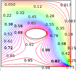
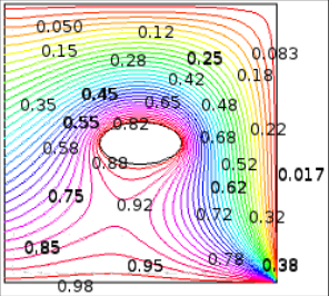
Conduction dominant heat transfer is observed from the isotherms in Fig. 5. We observed the isotherms line bending upper half of the square cavity for both cases. Comment to the both cases, isotherms lines are developed.

Figure 5. Illustrate the isotherms involving heated bottom moving wall, linearly heated left and right wall, upper cold moving wall and elliptic
Illustrate the isotherms involving heated bottom moving wall, linearly heated left and right wall, upper cold moving wall and elliptic↗ Enlarge
Figure 5
Illustrate the isotherms involving heated bottom moving wall, linearly heated left and right wall, upper cold moving wall and elliptic

Illustrate the isotherms involving heated bottom moving wall, linearly heated left and right wall, upper cold moving wall and elliptic

Open full-size image ↗
Original paper figureSource PDF · page 5 ↗

Effect of Darcy number

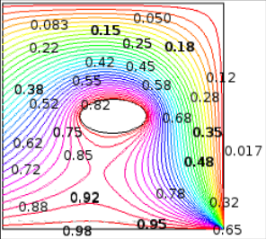
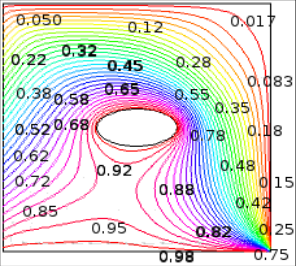
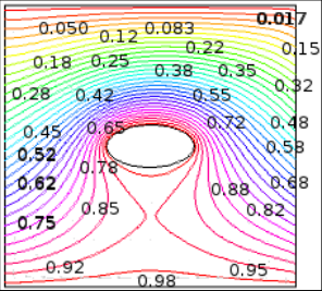
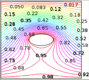
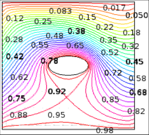
Variation of streamlines and isotherms of the lid-driven square cavity inside the elliptic shape block are shown in Fig. 7 and8, respectively. As can be seen from the streamlines in the Fig. 7

Figure 7. Streamlines and isotherms for linearly heated left walls and cold right wall with Pr = 0.7, Re = 100 and Gr = 105 for: (a) Da = 10-5; (b) Da
Streamlines and isotherms for linearly heated left walls and cold right wall with Pr = 0.7, Re = 100 and Gr = 105 for: (a) Da = 10-5; (b) Da↗ Enlarge
Figure 7
Streamlines and isotherms for linearly heated left walls and cold right wall with Pr = 0.7, Re = 100 and Gr = 105 for: (a) Da = 10-5; (b) Da

Streamlines and isotherms for linearly heated left walls and cold right wall with Pr = 0.7, Re = 100 and Gr = 105 for: (a) Da = 10-5; (b) Da

Open full-size image ↗
Original paper figureSource PDF · page 7 ↗

Conclusions

A numerical work has been done to simulate mixed convection in a lid-driven square cavity filled with porous medium with internal heated elliptic block with an electric conductive fluid with Prandtl number 0.7. Subsequently, a parametric study was performed and the effect of the Grashof number, Darcy number and Reynolds number on the fluid flow and heat transfer were investigated. The effect of varying the mentioned parameters on the distribution of streamlines, isotherms, average Nusselt number at the hot wall. For all cases considered, two counter rotating eddies were formed inside the cavity regardless of the Grashof numbers, Darcy numbers and Reynolds numbers. A heat generation parameter has a significant effect on streamlines during the mixed convection dominated regions. At the same time, it has a significant effect on thermal fields at the three convection regimes. The large values of Reynolds number lead to increase the lid-driven effect whereas the small values of Reynolds number lead to increase effect of presence of the heat source on the flow and heat characteristics. In addition, it was also observed that the isotherms are in general symmetric at smaller Pr irrespective of Da and Re at Gr = 10 5 for linearly heated left wall and cold right wall. Interesting results are obtained at higher Gr and Da with various regimes of Re. the isotherms are almost symmetric at small Re with higher Gr (Gr = 10 5 ) and Da = 10 -3 and mixed convection is found to be dominant whereas, forced convection leads to compressed isotherms near the left and bottom walls at higher Re for linearly heated side walls.

Acknowledgement

AcknowledgementsThe authors wish to acknowledge Department of Mathematics, Bangladesh University of Engineering and Technology (BUET), Dhaka-1000, Bangladesh, for support and technical help throughout this work.

Figures and tables from the paper

Figure 2. Effect of grid refinement test on average Nusselt number
Effect of grid refinement test on average Nusselt number↗ Enlarge
Figure 2
Effect of grid refinement test on average Nusselt number

Effect of grid refinement test on average Nusselt number

Open full-size image ↗
Original paper figureSource PDF · page 4 ↗
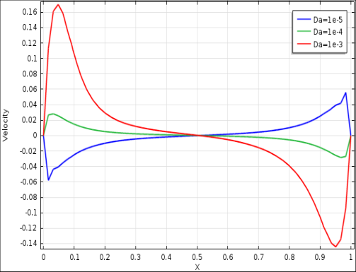
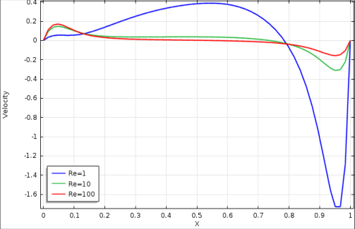
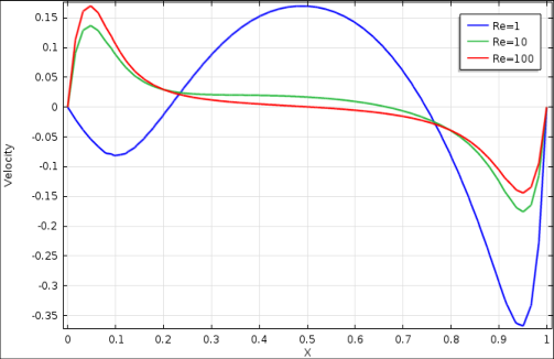
Figure 6. Variation of Local Nusselt number and Velocity of the square cavity with Grashof number Gr = 103 to 105.
Variation of Local Nusselt number and Velocity of the square cavity with Grashof number Gr = 103 to 105.↗ Enlarge
Figure 6
Variation of Local Nusselt number and Velocity of the square cavity with Grashof number Gr = 103 to 105.

Variation of Local Nusselt number and Velocity of the square cavity with Grashof number Gr = 103 to 105.

Open full-size image ↗
Original paper figureSource PDF · page 6 ↗
Figure 8. Isotherms for linearly heated left wall and cold right wall with Pr = 0.7, Re = 100 and Gr = 105 for: (a) Da = 10-5; (b) Da = 10-4; (c) Da =
Isotherms for linearly heated left wall and cold right wall with Pr = 0.7, Re = 100 and Gr = 105 for: (a) Da = 10-5; (b) Da = 10-4; (c) Da =↗ Enlarge
Figure 8
Isotherms for linearly heated left wall and cold right wall with Pr = 0.7, Re = 100 and Gr = 105 for: (a) Da = 10-5; (b) Da = 10-4; (c) Da =

Isotherms for linearly heated left wall and cold right wall with Pr = 0.7, Re = 100 and Gr = 105 for: (a) Da = 10-5; (b) Da = 10-4; (c) Da =

Open full-size image ↗
Original paper figureSource PDF · page 7 ↗
Figure 9. Variation of temperature gradient along the right wall of the square cavity with Darcy number
Variation of temperature gradient along the right wall of the square cavity with Darcy number↗ Enlarge
Figure 9
Variation of temperature gradient along the right wall of the square cavity with Darcy number

Variation of temperature gradient along the right wall of the square cavity with Darcy number

Open full-size image ↗
Original paper figureSource PDF · page 8 ↗
Figure 10. Streamlines and isotherms for linearly heated left wall and cold right wall with Pr = 0.7, Gr = 104 and Da = 10-3 for: (a) Re = 1; (b) Re =
Streamlines and isotherms for linearly heated left wall and cold right wall with Pr = 0.7, Gr = 104 and Da = 10-3 for: (a) Re = 1; (b) Re =↗ Enlarge
Figure 10
Streamlines and isotherms for linearly heated left wall and cold right wall with Pr = 0.7, Gr = 104 and Da = 10-3 for: (a) Re = 1; (b) Re =

Streamlines and isotherms for linearly heated left wall and cold right wall with Pr = 0.7, Gr = 104 and Da = 10-3 for: (a) Re = 1; (b) Re =

Open full-size image ↗
Original paper figureSource PDF · page 9 ↗
Figure 11. Isotherms for linearly heated left wall and cold right wall with Pr = 0.7, Gr = 104 and Da = 10-3 for: (a) Re = 1; (b) Re = 10; and (c) Re =
Isotherms for linearly heated left wall and cold right wall with Pr = 0.7, Gr = 104 and Da = 10-3 for: (a) Re = 1; (b) Re = 10; and (c) Re =↗ Enlarge
Figure 11
Isotherms for linearly heated left wall and cold right wall with Pr = 0.7, Gr = 104 and Da = 10-3 for: (a) Re = 1; (b) Re = 10; and (c) Re =

Isotherms for linearly heated left wall and cold right wall with Pr = 0.7, Gr = 104 and Da = 10-3 for: (a) Re = 1; (b) Re = 10; and (c) Re =

Open full-size image ↗
Original paper figureSource PDF · page 9 ↗
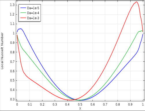
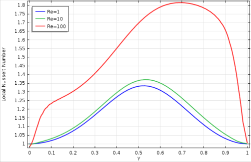
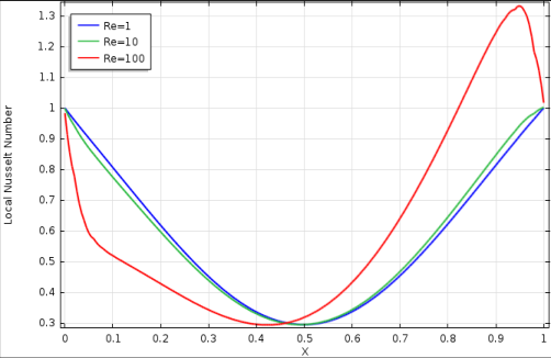
Figure 12. Variation of Local Nusselt number and dimensionless temperature along the right wall of the square cavity with Reynolds number
Variation of Local Nusselt number and dimensionless temperature along the right wall of the square cavity with Reynolds number↗ Enlarge
Figure 12
Variation of Local Nusselt number and dimensionless temperature along the right wall of the square cavity with Reynolds number

Variation of Local Nusselt number and dimensionless temperature along the right wall of the square cavity with Reynolds number

Open full-size image ↗
Original paper figureSource PDF · page 10 ↗
Figure 13. Variation of the average Nusselt number along the right wall of the square cavity with different Darcy numbers and Reynolds numbers
Variation of the average Nusselt number along the right wall of the square cavity with different Darcy numbers and Reynolds numbers↗ Enlarge
Figure 13
Variation of the average Nusselt number along the right wall of the square cavity with different Darcy numbers and Reynolds numbers

Variation of the average Nusselt number along the right wall of the square cavity with different Darcy numbers and Reynolds numbers

Open full-size image ↗
Original paper figureSource PDF · page 11 ↗
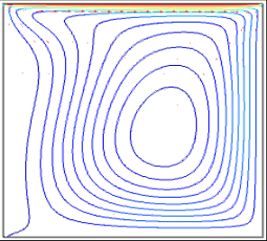
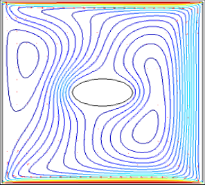
Figure 14. Streamline and isotherms for different Grashof number Present study (a) without obstacle (b) with elliptic obstacle
Streamline and isotherms for different Grashof number Present study (a) without obstacle (b) with elliptic obstacle↗ Enlarge
Figure 14
Streamline and isotherms for different Grashof number Present study (a) without obstacle (b) with elliptic obstacle

Streamline and isotherms for different Grashof number Present study (a) without obstacle (b) with elliptic obstacle

Open full-size image ↗
Original paper figureSource PDF · page 11 ↗

References

16 in the original paper
  1. Ingham DB, Pop I. (eds.), Transport phenomena in porous media, Pergamon, Oxford, UK, 1998.
  2. Bejan A. Convection Heat Transfer in Porous Media, in: Kakac S, Shah RK, Aung W. (eds.), Handbook of Single-Phase Convective Heat Transfer, John Wiley and Sons, New York, USA, 1987.
  3. Vafai K. Handbook of Porous Media, Marcel Dekker, New York, USA, 2000.
  4. Reddy JN. An Introduction to Finite Element Analysis, McGraw-Hill. New York, 1993.
  5. Zienkiewicz OC, Taylor RL, Too JM. Reduced integration technique in general analysis of plates and shells, Int. J Numer. Meth. Eng. 1971; 3:275-290.
  6. Basak T, Roy S, Paul T, Pop I. Numerical convection in a square cavity filled with a porous medium: effects of various thermal boundary conditions, Int. J Heat Mass Transfer. 2006; 49:1430-1441.
  7. Sathiyamoorthy M, Bask T, Roy S, Pop I. Steady natural convection flow in a square cavity filled with a porous medium for linearly heated side wall (s), Int. J Heat Mass Transfer. 2007; 50:1892-1901.
  8. Nield DA, Bejan A. Convection in Porous Media, third ed. Springer, Berlin, 2006.
  9. Ingham DB, Pop I. Transport Phenomena in Porous Media, Elsevier, Oxford, 2005, 3.
  10. Pop I, Ingham DB. Convective Heat Transfer: Mathematical and Computational Modeling of Viscous Fluids and Porous Media, Pergamon Press, Oxford, 2001.
  11. Bejan A, Dincer I, Lorente S, Miguel AF, Reis AH. Porous and Complex Flow Structures in Modern Technologies, Springer, New York, 2004.
  12. Oztop HF. Combined convection heat transfer in a porous lid-driven enclosure due to heater with finite length, Int. Commun. Heat Mass Transfer. 2006; 33:772-779.
  13. Chamka AJ, Khaled ARA. Nonsimilar hydromagnetic simulataneous heat and mass transfer by mixed convection from a vertical plate embedded in a uniform porous medium, Numer. Heat Transfer A. 1999; 36:327-344.
  14. Chamka AJ. Mixed convection flow along a vertical permeable plate embedded in a porous medium in the presence of a transverse magnetic field, Numer. Heat Transfer A. 1998; 34:93-103.
  15. Khanafer K, Chamka AJ. Mixed convection flow in a lid-driven enclosure filled with a fluid-saturated porous medium, Int. J Heat Mass Transfer. 1999; 42:2465-2481.
  16. Basak T, Roy S, Singh SK, Pop I. Analysis of mixed convection in a lid-driven porous square cavity with linearly heated side walls, Int. J Heat Mass Transfer. 2010; 53:1819-1840.